1-Mark Questions
QQuestion 1 1 Mark
A field excitation of 20 A in a certain alternator results in an armature current of 400 A in short circuit and a terminal voltage of 2000 V on open circuit. The magnitude of the internal voltage drop within the machine at a load current of 200 A is
AOptions
- 1 V
- 10 V
- 100 V
- 1000 V
SSolution
Given data:
- Field excitation: \(I_f = 20\) A
- Short circuit armature current: \(I_{SC} = 400\) A
- Open circuit voltage: \(V_{OC} = 2000\) V
- Load current: \(I_L = 200\) A
Synchronous impedance method:
From short circuit test at same field excitation:
This is the synchronous impedance of the machine.
Internal voltage drop:
At load current of 200 A, the internal voltage drop is:
This represents the voltage drop due to armature reaction and leakage reactance combined (synchronous reactance effect).
Physical interpretation:
- Open circuit: No load, terminal voltage = induced EMF
- Short circuit: Maximum current, zero terminal voltage
- At 200A load: Internal drop = 1000V reduces terminal voltage
Correct answer: D
QQuestion 2 1 Mark
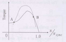
A 3-phase squirrel cage induction motor supplied from a balanced 3-phase source drives a mechanical load. The torque-speed characteristics of the motor (solid curve) and of the load (dotted curve) are shown. Of the two equilibrium points A and B, which of the following options correctly describes the stability of A and B?
AOptions
- A is stable, B is unstable
- A is unstable, B is stable
- Both are stable
- Both are unstable
SSolution
Stability criterion:
An equilibrium point is stable if a small perturbation in speed results in a restoring torque that returns the system to equilibrium.
Mathematical condition:
Analysis at point A:
Point A typically occurs on the stable operating region of the motor characteristic (between synchronous speed and maximum torque point):
- If speed increases slightly: \(T_{motor}\) decreases, \(T_{load}\) increases
- Net torque becomes negative (retarding)
- System returns to equilibrium
- If speed decreases: \(T_{motor}\) increases, \(T_{load}\) decreases
- Net torque becomes positive (accelerating)
- System returns to equilibrium
Point A is stable.
Analysis at point B:
Point B typically occurs on the unstable region (below maximum torque point, on negative slope):
- If speed increases slightly: \(T_{motor}\) increases more than \(T_{load}\)
- System accelerates further away from equilibrium
- If speed decreases: \(T_{motor}\) decreases more than \(T_{load}\)
- System decelerates further away from equilibrium
Point B is unstable.
Correct answer: A
QQuestion 3 1 Mark
An SCR is considered to be a semi-controlled device because
AOptions
- it can be turned OFF but not ON with a gate pulse
- it conducts only during one half-cycle of an alternating current wave
- it can be turned ON but not OFF with a gate pulse
- it can be turned ON only during one half-cycle of an alternating voltage wave
SSolution
SCR (Silicon Controlled Rectifier) characteristics:
Turn-ON capability:
- SCR can be turned ON by applying a gate pulse
- Gate pulse triggers the device from blocking to conducting state
- Once triggered, gate loses control
Turn-OFF capability:
- SCR cannot be turned OFF by gate signal
- Turn-off requires: (1) anode current < holding current, OR (2) reverse bias voltage
- Natural commutation: In AC circuits, current goes to zero at end of half cycle
- Forced commutation: External circuitry needed in DC applications
Why "semi-controlled"?
- Full control would mean: gate can both turn ON and turn OFF
- SCR has only partial (semi) control: gate can only turn ON
- Turn-OFF is not controllable by gate
- Contrasts with fully-controlled devices like:
- MOSFET: Gate controls both ON and OFF
- IGBT: Gate controls both ON and OFF
- GTO (Gate Turn-Off thyristor): Special SCR with turn-off capability
Analysis of options:
(A) Opposite - SCR can't be turned OFF with gate
(B) Incomplete - This describes rectifier action, not semi-controlled nature
(C) Correct - Captures the essence of semi-control: ON but not OFF
(D) Incomplete - Doesn't address the control aspect
Correct answer: C
2-Mark Questions
QQuestion 4 2 Mark
Transformer and emitter follower can both be used for impedance matching at the output of an audio amplifier. The basic relationship between the input power \(P_{in}\) and output power \(P_{out}\) in both the cases is
AOptions
- \(P_{in} = P_{out}\) for both transformer and emitter follower
- \(P_{in} > P_{out}\) for both transformer and emitter follower
- \(P_{in} < P_{out}\) for transformer and \(P_{in} = P_{out}\) for emitter follower
- \(P_{in} = P_{out}\) for transformer and \(P_{in} < P_{out}\) for emitter follower
SSolution
Transformer as impedance matcher:
Ideal transformer:
- No losses (100% efficiency)
- \(P_{in} = P_{out}\) (power conservation)
- \(V_1I_1 = V_2I_2\)
- Impedance transformation: \(Z_{in} = n^2Z_{out}\)
Real transformer:
- Small losses (copper, core)
- \(P_{in} \approx P_{out}\) (high efficiency, typically > 95%)
- For practical purposes: \(P_{in} \approx P_{out}\)
Emitter follower as impedance matcher:
Configuration:
- Common collector amplifier
- High input impedance, low output impedance
- Voltage gain \(\approx 1\)
Power relationships:
- Output power: \(P_{out} = V_{out}I_{out}\) (power delivered to load)
- Input power includes: Signal power + DC bias power
- The transistor requires DC supply power: \(P_{DC} = V_{CC}I_C\)
- Total input power > output power due to:
- Transistor losses (collector dissipation)
- Quiescent current consumption
- Biasing network losses
- Efficiency typically 25-50% for Class A operation
- Therefore: \(P_{in} > P_{out}\)
Comparison:
- Transformer: Passive device, nearly lossless
- Emitter follower: Active device, requires DC power, has losses
Correct answer: B
Both devices require more input power than output power, though transformer is much more efficient.
QQuestion 5 2 Mark
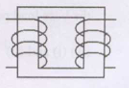
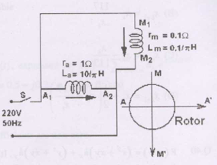
A 220 V, 50 Hz, single-phase induction motor has the following connection diagram and winding orientations shown. MM' is the axis of the main stator winding (M1M2) and AA' is that of the auxiliary winding (A1A2). Directions of the winding axes indicate direction of flux when currents in the windings are in the directions shown. Parameters of each winding are indicated. When switch S is closed, the motor
AOptions
- rotates clockwise
- rotates anticlockwise
- does not rotate
- rotates momentarily and comes to a halt
SSolution
Single-phase induction motor starting:
Problem with single-phase:
- Single-phase supply creates pulsating field (not rotating)
- No starting torque produced
- Motor won't self-start
Solution - Split-phase with capacitor:
When switch S is closed:
- Main winding: Connected directly to supply
- Auxiliary winding: Connected through capacitor
Phase relationship:
- Main winding current: \(I_m\) (nearly in phase with voltage, slightly lagging)
- Auxiliary winding current: \(I_a\) (leads voltage due to capacitor)
- Phase difference created between \(I_m\) and \(I_a\)
- Two currents displaced in phase create rotating magnetic field
Direction of rotation:
The direction depends on:
- Spatial position of windings (MM' and AA' axes)
- Phase sequence of currents
- With capacitor: auxiliary current leads main current
- If auxiliary axis leads main axis spatially, and current leads in time
- Creates forward rotating field
From the circuit configuration and standard conventions, with capacitor start: Motor will rotate in a specific direction (typically anticlockwise for standard connection).
Why it won't stop:
- Once started, even if auxiliary winding disconnected, motor continues
- Single-phase induction motor has no starting torque but has running torque
- The rotating field from two phases gets it started
Correct answer: B (rotates anticlockwise)
Note: Exact direction depends on winding connections shown in figure.