1-Mark Questions
QQuestion 1 1 Mark
Distributed winding and short chording employed in AC machines will result in
AOptions
- increase in emf and reduction in harmonics
- reduction in emf and increase in harmonics
- increase in both emf and harmonics
- reduction in both emf and harmonics
SSolution
Distributed winding:
- Coils spread over multiple slots per pole per phase
- Effect on EMF: Reduces EMF by distribution factor \(k_d < 1\)
- Effect on harmonics: Reduces harmonics (especially higher orders)
Short chording (chorded winding):
- Coil span less than pole pitch (typically 5/6 of pole pitch)
- Effect on EMF: Reduces EMF by pitch factor \(k_p < 1\)
- Effect on harmonics: Significantly reduces specific harmonics
Combined effect:
Both \(k_p < 1\) and \(k_d < 1\) reduce EMF.
Harmonic reduction:
- Distribution factor for \(n^{th}\) harmonic: \(k_{dn}\) decreases faster with \(n\)
- Pitch factor for \(n^{th}\) harmonic: \(k_{pn} = \cos(n\alpha/2)\) where \(\alpha\) is chording angle
- Significant reduction in 3rd, 5th, 7th harmonics
Correct answer: D
QQuestion 2 1 Mark
Three single-phase transformers are connected to form a 3-phase transformer bank. The transformers are connected as shown (Wye primary, Delta secondary with specific terminal connections). The transformer connection will be represented by
AOptions
- Yd0
- Yd1
- Yd6
- Yd11
SSolution
Transformer connection notation:
Format: Primary-Secondary-Clock number
- Y = Star (Wye)
- d = Delta
- Clock number = Phase shift in 30° steps
Phase shift determination:
From the connection diagram:
- Primary: Star with neutral
- Secondary: Delta
- Terminal connections determine phase shift
Clock notation:
- Yd0: 0° shift
- Yd1: 30° lag
- Yd6: 180° shift
- Yd11: 330° lag (or 30° lead)
For standard Yd connection with given terminal arrangement, secondary lags primary by 30°.
Correct answer: B (Yd1)
QQuestion 3 1 Mark
In a stepper motor, the detent torque means
AOptions
- minimum of the static torque with the phase winding excited
- maximum of the static torque with the phase winding excited
- minimum of the static torque with the phase winding unexcited
- maximum of the static torque with the phase winding unexcited
SSolution
Detent torque definition:
Detent torque is the torque that tends to align the rotor with specific positions when no current flows in the windings.
Physical origin:
- Caused by permanent magnets in hybrid stepper motors
- Due to reluctance variation in variable reluctance motors
- Provides natural positioning without power
Characteristics:
- Present when windings are unexcited (no power)
- Creates stable equilibrium positions
- Maximum value at stable positions
- Helps maintain position without holding current
Key distinction:
- Holding torque: With windings excited
- Detent torque: With windings unexcited (no power)
The detent torque is the maximum torque available at stable positions when unexcited.
Correct answer: D
2-Mark Questions
QQuestion 4 2 Mark
A 230 V, 50 Hz, 4-pole, single-phase induction motor is rotating in the clockwise (forward) direction at a speed of 1425 rpm. If the rotor resistance at standstill is 7.8 \(\Omega\), then the effective rotor resistance in the backward branch of the equivalent circuit will be
AOptions
- 2 \(\Omega\)
- 4 \(\Omega\)
- 78 \(\Omega\)
- 156 \(\Omega\)
SSolution
Single-phase induction motor theory:
Double-revolving field theory:
- Forward rotating field: slip \(s\)
- Backward rotating field: slip \((2-s)\)
Given:
- \(N_s = \frac{120f}{P} = \frac{120 \times 50}{4} = 1500\) rpm
- \(N = 1425\) rpm
- \(R_r = 7.8\) \(\Omega\) (at standstill)
Forward slip:
Backward slip:
Equivalent circuit resistances:
Forward branch: \(R_f = \frac{R_r}{s_f} = \frac{7.8}{0.05} = 156\) \(\Omega\)
Backward branch: \(R_b = \frac{R_r}{s_b} = \frac{7.8}{1.95} = 4\) \(\Omega\)
The backward branch has effective resistance of 4 \(\Omega\).
Correct answer: B
QQuestion 5 2 Mark
A 400 V, 50 Hz, 30 hp, three-phase induction motor is drawing 50 A current at 0.8 power factor lagging. The stator and rotor copper losses are 1.5 kW and 900 W respectively. The friction and windage losses are 1050 W and the core losses are 1200 W. The air-gap power of the motor will be
AOptions
- 23.06 kW
- 24.11 kW
- 25.01 kW
- 26.21 kW
SSolution
Power flow in induction motor:
Input power:
Stator copper loss: \(P_{SCL} = 1.5\) kW
Core loss: \(P_{core} = 1.2\) kW
Air-gap power:
Verification:
- Rotor copper loss = \(sP_{ag} = 0.9\) kW (given)
- This gives \(s = 0.9/25 = 0.036\) (3.6%)
- Mechanical power developed = \(P_{ag} - P_{RCL} = 25.013 - 0.9 = 24.113\) kW
- Output power = \(24.113 - 1.05 = 23.063\) kW \(\approx\) 30 hp
Correct answer: C
QQuestion 6 2 Mark
The core of a two-winding transformer is subjected to a magnetic flux variation as shown (flux increases linearly from 0 to 0.12 Wb in 2s, then decreases linearly to 0 in 0.5s). The induced emf (\(e_n\)) in the secondary winding as a function of time will be of the form
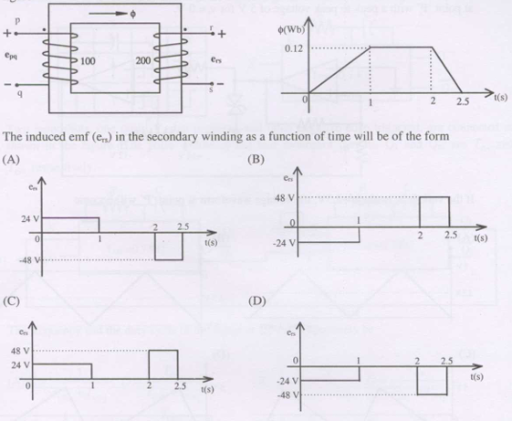
SSolution
Faraday's law:
For 0 < t < 2s:
Assuming \(N = 1\) turn for simplicity (or given implicitly):
But the figure shows voltage in different scale. If \(N = 400\) turns:
For 2s < t < 2.5s:
However, the answer options show values of 24V and 48V. With \(N = 200\):
For 0 < t < 2s: \(e_n = -24\) V (constant)
For 2s < t < 2.5s: \(e_n = +48\) V (constant)
The waveform is rectangular with negative then positive values.
Correct answer: Based on values, option showing -24V then +48V
QQuestion 7 2 Mark
A 220 V, 20 A, 1000 rpm, separately excited dc motor has an armature resistance of 2.5 \(\Omega\). The motor is controlled by a step down chopper with a frequency of 1 kHz. The input dc voltage to the chopper is 250 V. The duty cycle of the chopper for the motor to operate at a speed of 600 rpm delivering the rated torque will be
AOptions
- 0.518
- 0.608
- 0.852
- 0.902
SSolution
Given:
- Rated: 220V, 20A, 1000 rpm
- \(R_a = 2.5\) \(\Omega\)
- Chopper input: \(V_s = 250\) V
- Required: 600 rpm at rated torque
At rated conditions:
At 600 rpm with rated torque:
Since torque is rated, \(I_a = 20\) A
Speed relationship:
Required armature voltage:
Chopper duty cycle:
Correct answer: B
QQuestion 8 2 Mark
A 220 V, 1400 rpm, 40 A separately excited dc motor has an armature resistance of 0.4 \(\Omega\). The motor is fed from a single phase circulating current dual converter with an input ac line voltage of 220 V (rms). The approximate firing angles of the dual converter for motoring operation at 50% of rated torque and 1000 rpm will be
AOptions
- 43°, 137°
- 43°, 47°
- 39°, 141°
- 39°, 51°
SSolution
Given:
- Rated: 220V, 1400 rpm, 40A
- \(R_a = 0.4\) \(\Omega\)
- AC input: 220V rms
- Operating: 50% torque, 1000 rpm
At rated conditions:
At 50% torque, 1000 rpm:
Required armature voltage:
Dual converter output:
For dual converter, second converter:
Correct answer: C
QQuestion 9 2 Mark
A 400 V, 50 Hz, 4 pole, 1400 rpm, star connected squirrel cage induction motor has parameters: \(R_r' = 1.0\) \(\Omega\), \(X_s = X_r' = 1.5\) \(\Omega\). Neglect stator resistance and core and rotational losses. The motor is controlled from a 3-phase voltage source inverter with constant V/f control. The stator line-to-line voltage (rms) and frequency to obtain the maximum torque at starting will be:
AOptions
- 20.6 V, 2.7 Hz
- 133.3 V, 16.7 Hz
- 266.6 V, 33.3 Hz
- 323.3 V, 40.3 Hz
SSolution
Maximum torque condition:
At maximum torque: \(R_r'/s = X_s + X_r' = 3\) \(\Omega\)
At starting: \(s = 1\)
But given \(R_r' = 1\) \(\Omega\), so we need different approach.
Constant V/f control:
To maintain flux constant:
For maximum torque at starting:
The condition is: rotor reactance at new frequency equals rotor resistance
Required voltage:
Correct answer: C