Kirchhoff’s Laws
Kirchhoff’s Current Law (KCL)
The algebraic sum of currents entering a node is zero.
Mathematical Form:
Alternative Form:
Physical Basis: Conservation of charge
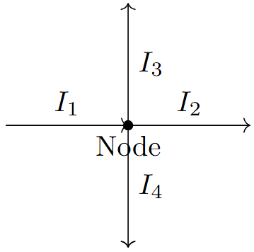
Example: \(I_1 - I_2 - I_3 - I_4 = 0\)
Sign convention: Current entering = +ve, Current leaving = -ve
Kirchhoff’s Voltage Law (KVL)
The algebraic sum of voltages around any closed loop is zero.
Mathematical Form:
Physical Basis: Conservation of energy
Steps:
-
Choose loop direction
-
Apply sign convention
-
Write KVL equation
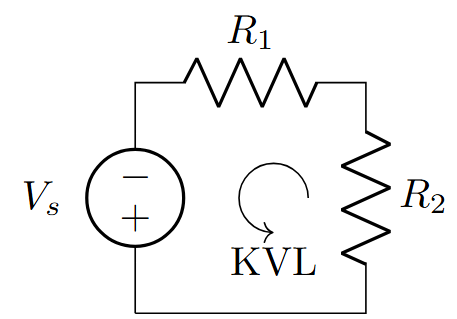
Example: \(V_s - I R_1 - I R_2 = 0\)
Voltage rise = +ve, Voltage drop = -ve (or vice versa, be consistent)
Circuit Analysis Methods
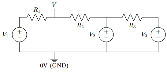
Nodal Analysis
-
Select reference node (ground)
-
Assign node voltages
-
Apply KCL at each non-reference node
-
Solve simultaneous equations
For node with voltage \(V_n\):
Supernode: When voltage source connects two non-reference nodes
-
More current sources than voltage sources
-
Number of nodes < Number of meshes
-
Circuits with supernodes
GATE Formula: For n nodes, write (n-1) KCL equations
Mesh Analysis
-
Identify independent meshes
-
Assign mesh currents (clockwise)
-
Apply KVL to each mesh
-
Solve simultaneous equations
For mesh with current \(I_m\):
Supermesh: When current source is common to two meshes
-
More voltage sources than current sources
-
Number of meshes < Number of nodes
-
Planar circuits only
GATE Formula: For planar circuit: Meshes = Branches - Nodes + 1
Network Theorems
Superposition Theorem
In a linear circuit with multiple sources, the response is the algebraic sum of responses due to individual sources acting alone.
-
Consider one source at a time
-
Replace other voltage sources with short circuits
-
Replace other current sources with open circuits
-
Calculate response due to active source
-
Repeat for all sources
-
Add all responses algebraically
-
Applicable only to LINEAR circuits
-
Power cannot be calculated using superposition
-
Dependent sources remain active
-
\(P_{total} \neq P_1 + P_2 + ... + P_n\)
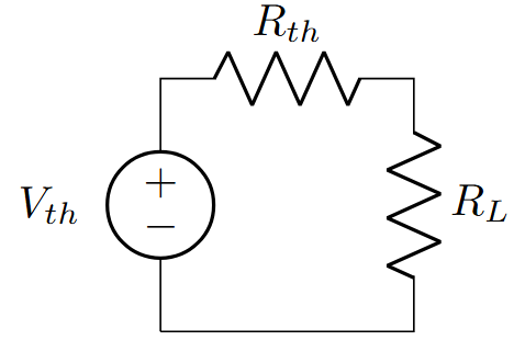
Thevenin’s Theorem
Any linear two-terminal network can be replaced by a voltage source \(V_{th}\) in series with resistance \(R_{th}\).
Steps:
-
Remove load resistance
-
Find \(V_{th}\) = Open circuit voltage
-
Find \(R_{th}\):
-
Kill independent sources
-
Look back into terminals
-
For dependent sources: \(R_{th} = \dfrac{V_{test}}{I_{test}}\)
-
-
Draw Thevenin equivalent
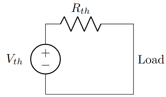
Alternative method: \(R_{th} = \dfrac{V_{oc}}{I_{sc}}\) (open circuit voltage / short circuit current)
Norton’s Theorem
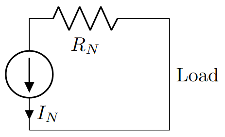
Any linear two-terminal network can be replaced by a current source \(I_N\) in parallel with resistance \(R_N\).
Steps:
-
Remove load resistance
-
Find \(I_N\) = Short circuit current
-
Find \(R_N = R_{th}\)
-
Draw Norton equivalent
Source Transformation:
Norton and Thevenin are dual theorems. Use Norton when current calculation is easier.
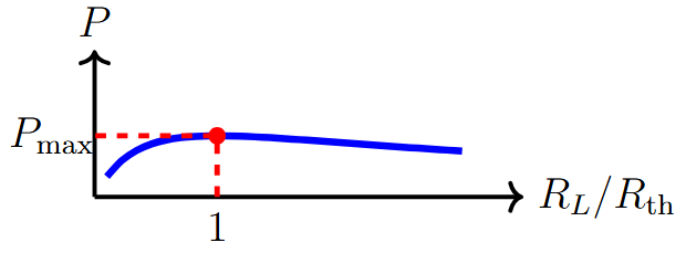
Maximum Power Transfer Theorem
Maximum power is transferred to load when load resistance equals source resistance.
Condition: \(R_L = R_{th}\)
Maximum Power:
Load Current:
Efficiency at Maximum Power:
For AC circuits: \(Z_L = Z_{th}^*\) (complex conjugate matching)
Additional Important Theorems
Reciprocity Theorem
In a linear, bilateral network, if a voltage source in branch A produces current in branch B, then the same voltage source in branch B will produce the same current in branch A.
Mathematical Form:
Transfer Impedance:
-
Linear network
-
Bilateral elements (R, L, C)
-
No dependent sources
-
Same frequency for AC analysis
GATE Application: Useful in analyzing two-port networks and transmission lines.
Millman’s Theorem
Used to find voltage across parallel branches with different voltage sources.
Formula:
where \(V_k\) are source voltages, \(R_k\) are branch resistances, and \(G_k = \dfrac{1}{R_k}\) (conductance).
GATE Tip: Very useful for parallel voltage divider circuits and finding common voltage.
Compensation Theorem
When impedance in any branch changes from \(Z_1\) to \(Z_2\), the change in current can be calculated by considering a compensating voltage source.
Compensating Voltage:
where \(I_1\) is the original current through the branch.
Change in Current:
-
Fault analysis in power systems
-
Incremental analysis of circuits
-
Sensitivity analysis
-
Finding change in circuit parameters
GATE Usage: Useful for analyzing the effect of component variations on circuit behavior.
Substitution Theorem
Any branch in a network can be replaced by an equivalent branch that has the same voltage across it and current through it.
Equivalent Replacements:
-
Voltage source = Branch voltage (\(V_s = V_{branch}\))
-
Current source = Branch current (\(I_s = I_{branch}\))
-
Impedance = \(Z_{eq} = \dfrac{V_{branch}}{I_{branch}}\)
Very useful for:
-
Simplifying complex circuits
-
Finding equivalent circuits
-
Network reduction techniques
-
Analyzing one part of circuit independently
Note: The rest of the circuit behavior remains unchanged.
Tellegen’s Theorem
In any lumped network, the sum of instantaneous powers delivered to all branches is zero.
Mathematical Form:
Physical Interpretation: Total power generated = Total power consumed
-
Power balance verification
-
Network analysis validation
-
Fundamental theorem for all network theorems
-
Circuit simulation algorithms
Tellegen’s theorem is the most fundamental theorem - all other network theorems can be derived from it.
Star-Delta Transformation
Any three-terminal star (Y) network can be transformed to equivalent delta (\(\Delta\)) network and vice versa.
Star to Delta:
General Form:
Delta to Star:
General Form:
For equal resistances: \(R_Y = \dfrac{R_\Delta}{3}\) and \(R_\Delta = 3R_Y\)
Advanced Concepts
Dependent Sources and Network Theorems
-
Dependent sources are never killed/deactivated
-
They remain active during Thevenin/Norton analysis
-
Superposition: Only independent sources are considered one at a time
-
For \(R_{th}\) with dependent sources: Apply test voltage/current method
Test Source Method:
-
Kill all independent sources
-
Apply test voltage \(V_t\) (or current \(I_t\))
-
Calculate resulting current \(I_t\) (or voltage \(V_t\))
-
\(R_{th} = \dfrac{V_t}{I_t}\)
Students often try to kill dependent sources - this is incorrect!
AC Circuit Analysis
All theorems apply to AC circuits using complex impedances:
-
Resistance \(R ~\to\) Impedance \(Z\)
-
DC voltage/current \(\to\) Phasor voltage/current
-
\(R_{th}\) becomes \(Z_{th}\)
Maximum Power Transfer (AC):
Phasor Analysis:
-
Use \(j\omega L\) for inductors
-
Use \(\dfrac{1}{j\omega C}\) for capacitors
-
All calculations in complex domain
For purely resistive loads: \(R_L = |Z_{th}|\) for maximum power transfer
Quick Reference
GATE Quick Reference Card
-
KCL: \(\sum I = 0\) at any node
-
KVL: \(\sum V = 0\) around any loop
-
Thevenin: \(V_{th}\) (open circuit), \(R_{th}\) (kill sources or \(V_{oc}/I_{sc}\))
-
Norton: \(I_N\) (short circuit), \(R_N = R_{th}\)
-
Max Power: \(R_L = R_{th}\), \(P_{max} = \dfrac{V_{th}^2}{4R_{th}}\), \(\eta = 50\%\)
-
Millman: \(V = \dfrac{\sum G_k V_k}{\sum G_k}\)
-
Star-Delta: \(R_Y = \dfrac{R_\Delta}{3}\) (equal resistances)
-
Nodal: More current sources, fewer nodes
-
Mesh: More voltage sources, planar circuit
-
Thevenin/Norton: Load analysis, source equivalents
-
Superposition: Multiple sources, linear circuits
-
Star-Delta: Non-planar circuits, bridge circuits
Common GATE Problem Types
-
Direct Application: Find current/voltage using specific theorem
-
Equivalent Circuits: Thevenin/Norton equivalents
-
Maximum Power: Load resistance and power calculations
-
Comparative Analysis: Which method is most efficient?
-
Mixed Circuits: AC and DC sources, dependent sources
-
Network Simplification: Using multiple theorems
-
Killing dependent sources in Thevenin analysis
-
Using superposition for power calculations
-
Wrong sign conventions in KCL/KVL
-
Forgetting complex conjugate in AC maximum power transfer
-
Not considering all constraint equations in supernode/supermesh
Time-Saving Techniques
-
Voltage Divider: \(V_R = V_s \dfrac{R}{R_{total}}\)
-
Current Divider: \(I_R = I_s \dfrac{R_{other}}{R + R_{other}}\)
-
Source Transformation: Convert between voltage and current sources
-
Series/Parallel Combinations: Simplify before applying theorems
-
Symmetry: Use circuit symmetry to reduce calculations
-
Identify the quickest method first (30 seconds)
-
Check if answer choices give clues about approach
-
Use approximations when exact values aren’t needed
-
Verify answers using alternative methods if time permits
Memory Aids
-
KCL: "Current In = Current Out"
-
KVL: "Voltage Rises = Voltage Falls"
-
Thevenin: "Open circuit voltage, Kill sources for resistance"
-
Norton: "Short circuit current, Same resistance"
-
Max Power: "Match the load, Get half efficiency"
-
Superposition: "One source at a time, others killed"
-
Power balance: \(\sum P_{generated} = \sum P_{consumed}\)
-
Dimension analysis: Check units in final answer
-
Limiting cases: What happens when \(R \to 0\) or \(R \to \infty\)?
-
Symmetry: Equal components should have equal currents/voltages