Zener Diode as Voltage Regulator
Zener Effect vs. Avalanche Effect
Zener Effect:
Occurs in heavily doped diodes with a narrow depletion layer.
Electric field becomes intense, approximately 300,000 V/cm.
Field pulls electrons from valence orbits (known as high-field emission).
Dominates in breakdown voltages less than 4 V.
Avalanche Effect:
Minority carriers are accelerated, dislodging other electrons.
Causes an avalanche of free carriers, resulting in large reverse current.
Dominates in breakdown voltages greater than 6 V.
Between 4-6 V:
Both Zener and Avalanche effects are present.
Naming:
Historically, all breakdown diodes are called Zener diodes, even though both effects may occur.
Temperature Coefficients in Zener Diodes
Impact of Temperature on Zener Voltage:
Zener voltage changes with ambient temperature.
Listed in data sheets as the temperature coefficient:
Change in breakdown voltage per degree Celsius (\(^{\circ}\mathrm{C}\)).
Breakdown Voltage \(<\) 4 V:
Negative temperature coefficient (Zener effect).
Example: A 3.9 V zener diode may have a coefficient of -1.4 mV/\(^{\circ}\mathrm{C}\).
For each \(1^{\circ}~\mathrm{C}\) increase, breakdown voltage decreases by 1.4 mV.
Breakdown Voltage \(>\) 6 V:
Positive temperature coefficient (Avalanche effect).
Example: A 6.2 V zener diode may have a coefficient of +2 mV/\(^{\circ}\mathrm{C}\).
For each \(1^{\circ}\mathrm{C}\) increase, breakdown voltage increases by 2 mV.
Between 4 and 6 V:
Temperature coefficient shifts from negative to positive.
Some diodes have a zero temperature coefficient, offering stability across temperature ranges.
Important for applications needing stable Zener voltage over wide temperature variations.
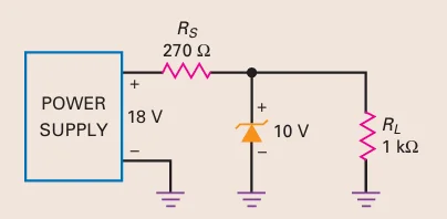
Problem-2
Is the zener diode operating in the breakdown region?

The Thevenin voltage (\(V_{th}\)) is greater than the Zener voltage (\(V_Z\)).
Operates in the breakdown region.
Problem-3
What is the zener current?
Problem-4
What is the behaviour of this circuit?

First Zener diode acts as a preregulator.
Second Zener diode serves as a Zener regulator.
Preregulator output: 20 V.
Zener regulator output: 10 V.
Provide the second regulator with a well-regulated input.
Ensure the final output is extremely well regulated.
Problem-5

Zener diodes are commonly used in voltage regulators, remaining in the breakdown region.
Zener diodes can be utilized in circuits for waveshaping, as shown in the configuration with two back-to-back Zener diodes.
Positive Half-Cycle:
Upper diode conducts; lower diode breaks down.
Output is clipped at \(\text{Zener Voltage} + 0.7 \, \text{V}\).
Negative Half-Cycle:
Lower diode conducts; upper diode breaks down.
Output approaches a square wave.
Conclusion:
Larger input sine waves produce a better-shaped output square wave.
Problem-6
Multiple DC Output Voltages:

Combination of zener diodes and ordinary silicon diodes used to generate multiple DC output voltages from a 20-V power supply.
Bottom diode produces 10 V output.
Forward-biased silicon diodes add small voltage steps: 10.7 V and 11.4 V.
Top zener diode with a 2.4 V breakdown voltage gives an output of 13.8 V.
Different combinations of zener and silicon diodes can yield various DC outputs.
Over-voltage Protection:

If a 6-V relay is connected directly to a 12-V supply, it might be damaged.
Solution is to connect a 5.6-V zener diode in series with the relay.
Zener diode drops 5.6 V, leaving 6.4 V across the relay (within tolerance).
Capacitor Over-voltage Protection:

Electrolytic capacitors often have low voltage ratings (e.g., 1000 \(\mu\)F, rated at 6 V).
If used with a 12-V supply, the capacitor could be damaged.
By placing a 6.8-V zener diode in series, the voltage across the capacitor is reduced to 5.2 V, safely within its 6-V rating.