Other Specialized Diodes
Varistors
Current-Regulator Diodes
Step-Recovery Diodes
Back Diodes
Tunnel Diodes
PIN Diodes
Varistor – Protecting Against Voltage Spikes
Overview:
AC Line Transients:
Power-line faults, lightning, and transients can introduce voltage dips and spikes on the AC line.
Spikes: Short overvoltage events, sometimes reaching up to 2000 V or more.
Dips: Severe voltage drops, lasting microseconds or less.
Varistor Functionality:
What is a Varistor?
A varistor acts as a transient suppressor to protect against voltage spikes.
Similar to two back-to-back Zener diodes, with high breakdown voltage in both directions.
Breakdown Voltage:
Varistors are available with breakdown voltages from 10 V to 1000 V.
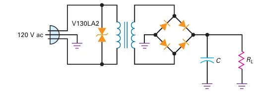
For example, V130LA2 has a breakdown voltage of 184 V and can handle 400 A peak current.
Protection Mechanism:
Spikes Clipping:
When connected across a power line, the varistor clips voltage spikes at the breakdown level.
Example: V130LA2 clips spikes above 184 V, protecting the equipment from overvoltage damage.
Applications:
AC Line Filtering:
Varistors are used in filters to protect transformers and power supplies from line transients.
Common in devices like surge protectors and line conditioners to ensure stable power supply.
Current-Regulator Diodes – Ensuring Constant Current
Overview:
Functionality:
Unlike Zener diodes that regulate voltage, current-regulator diodes maintain a constant current regardless of changes in voltage or load.
These diodes ensure a fixed current flow over a wide range of voltages.
Schematic Symbol:
Symbol Representation:
The schematic symbol of a current-regulator diode is shown with an arrow pointing upward, indicating control of current.
Operation:
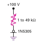
Example: 1N5305
Holds a constant 2 mA current over a voltage range of 2 to 100 V.
The current remains steady even if the load resistance varies significantly (e.g., from 1 to 49 k\(\Omega\)).
Applications:
Use Cases:
Ideal for current-limiting in LED circuits, biasing transistors, and ensuring stable current in various electronic applications.
Helps protect circuits from fluctuating load conditions while maintaining a fixed output current.
Step-Recovery Diodes – The Snap Effect for Frequency Multiplication
Overview:
Special Diode Behavior:
Known for its "snap-off" characteristic during reverse recovery.
Alternate name: Snap Diode due to the sudden reverse current cutoff.
Schematic Symbol:
Schematic Representation:
The symbol of a step-recovery diode includes a diode with a rectangular-shaped section, indicating its step-recovery behavior.
Operation:
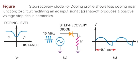
Unique Doping Profile:
The carrier density decreases near the junction, leading to the reverse snap-off phenomenon.
Current Behavior:
Forward conduction during the positive half-cycle like a regular silicon diode.
During the negative half-cycle, reverse current flows for a short time, then snaps to zero.
The sudden step in current is rich in harmonics, which can be filtered to produce higher frequencies.
Applications:
Frequency Multipliers:
By generating harmonics (multiples of the input frequency like 2fin, 3fin, and 4fin), step-recovery diodes are widely used in frequency multiplier circuits.
These diodes convert the input frequency into a higher frequency sine wave through harmonic filtering.
Back Diodes – Efficient Rectification of Weak Signals
Overview:
Special Diode Behavior:
Back diodes are diodes that conduct better in reverse than in forward direction.
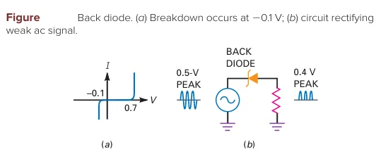
Designed with very low reverse breakdown voltages (around 0.1 V).
Schematic Symbol:
Zener-like Symbol:
The symbol for a back diode resembles that of a zener diode to indicate its reverse conduction behavior.
Operation:
Doping Levels:
Heavily doped diodes that show zener effect close to zero voltage.
Forward conduction occurs near 0.7 V, while reverse breakdown starts at approximately 0.1 V.
Rectification of Weak Signals:
Useful for signals where the peak amplitude is between 0.1 V and 0.7 V.
Example: A 0.5 V sine wave drives a back diode and load resistor.
The diode does not conduct in the forward direction because 0.5 V is not enough to turn it on.
However, it breaks down in reverse, rectifying the signal, producing a half-wave signal with a peak of 0.4 V.
Applications:
Weak Signal Rectification:
Back diodes are occasionally used in circuits to rectify low-amplitude signals, where traditional diodes would not be effective.
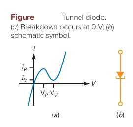
Tunnel Diodes – Mastering Negative Resistance
Overview:
Tunnel diodes are heavily doped diodes that exhibit negative resistance in forward conduction.
Breakdown can occur at 0 V due to extreme doping levels.
Schematic Symbol:
The tunnel diode symbol indicates its unique behavior.
Operation:
Distorted I-V Curve:
In forward bias, the diode demonstrates an unusual curve with a negative resistance region.
Negative resistance occurs between the peak point \((V_P)\) and valley point \((V_V)\).
In this region, an increase in voltage results in a decrease in current.
Oscillation:
This negative resistance property is key for creating high-frequency oscillators that generate sinusoidal signals.
Applications:
Oscillators:
Tunnel diodes are used in high-frequency oscillator circuits, which can convert dc energy into sinusoidal signals.
Unlike traditional generators, they don’t require mechanical energy.
PIN Diodes – Variable Resistor for RF and Microwave Applications
Overview:
PIN diodes consist of an intrinsic (i) semiconductor material placed between p-type and n-type regions.
The unique structure allows them to operate as a variable resistor at RF and microwave frequencies.
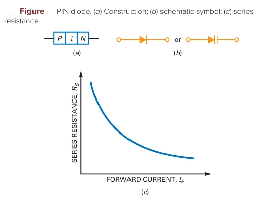
Operation:
Forward Bias:
Acts as a current-controlled resistor.
As the forward current increases, the series resistance decreases.
Reverse Bias:
Functions as a fixed capacitor when reverse biased, making it useful in high-frequency applications.
Schematic Symbol:
The PIN diode symbol represents its functionality.
Applications:
Modulator Circuits:
Widely used in RF and microwave modulation systems due to its controllable resistance characteristics.
Special-Purpose Devices
| Device | Key Idea | Application |
|---|---|---|
| Zener diode | Operates in breakdown region | Voltage regulators |
| LED | Emits noncoherent light | DC or AC indicators, efficient light source |
| Seven-segment indicator | Can display numbers | Measuring instruments |
| Photodiode | Light produces minority carriers | Light detectors |
| Optocoupler | Combines LED and photodiode | Input/output isolators |
| Laser diode | Emits coherent light | CD/DVD players, broadband communications |
| Schottky diode | Has no charge storage | High-frequency rectifiers (300 MHz) |
| Varactor | Acts like variable capacitance | TV and receiver tuners |
| Varistor | Breaks down both ways | Line-spike protectors |
| Current-regulator diode | Holds current constant | Current regulators |
| Step-recovery diode | Snaps off during reverse conduction | Frequency multipliers |
| Back diode | Conducts better in reverse | Weak-signal rectifiers |
| Tunnel diode | Has a negative-resistance region | High-frequency oscillators |
| PIN diode | Controlled resistance | Microwave communications |