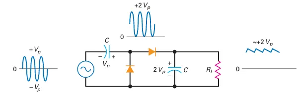
Peak-to-Peak Detector
Half-Wave Rectifier with Capacitor-Input Filter:
Produces a DC output voltage approximately equal to the peak of the input signal.
Peak Detector:
A small-signal diode converts the rectifier into a peak detector.
Operates at higher frequencies than 60 Hz.
Used in measurements, signal processing, and communications.
Peak-to-Peak Detector:
Cascades a clamper with a peak detector.
The output of the clamper is the input to the peak detector.
The peak detector provides a DC voltage equal to \(2V_p\).
RC Time Constant:
Must be much greater than the period of the signal for effective clamping and peak detection.
Ensures small output ripple.
Application: Measuring Nonsinusoidal Signals:
Ordinary AC voltmeters read RMS value; incorrect for nonsinusoidal signals.
A peak-to-peak detector’s output to a DC voltmeter shows the peak-to-peak voltage.
Example: For a signal swinging from -20V to +50V, the reading will be 70V.
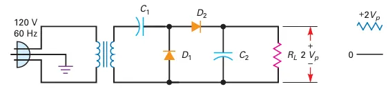
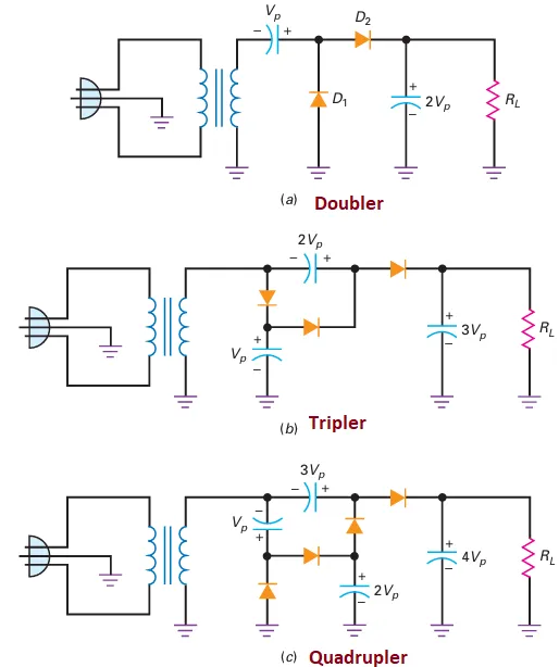
Voltage Multipliers: Voltage Doubler
Voltage Multipliers:
Uses rectifier diodes and operates at 60 Hz.
Produces higher DC output voltages using configurations like the voltage doubler.
Voltage Doubler:
Similar configuration to a peak-to-peak detector.
Clamper adds a DC component to the secondary voltage.
Peak detector produces DC output voltage twice the secondary voltage.
Why Use a Voltage Doubler?
Adjusting the turns ratio works for lower voltages.
For very high DC output voltages, using a step-up transformer alone can be bulky and impractical.
Voltage doublers allow for smaller transformers and simpler designs.
Example:
Line voltage: 120 V rms (170 V peak).
To achieve 3400 V DC: Requires a 1:20 step-up transformer.
Using a voltage doubler can reduce transformer size and complexity.
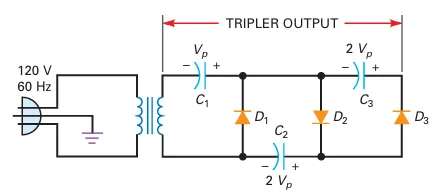
Voltage Multipliers: Tripler
Voltage Tripler:
Adds an additional section to the doubler circuit.
At the peak of the negative half-cycle, D3 forward biases, charging C3 to 2Vp.
Output voltage appears across \(C_1\) and \(C_3\).
The output voltage is approximately 3Vp with a long time constant.
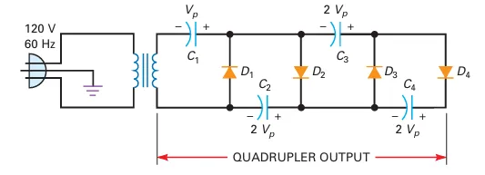
Voltage Multipliers: Quadrupler
Voltage Quadrupler:
Composed of four sections in cascade.
The first three sections form a tripler; the fourth section adds another \(V_p\).
Output voltage appears across \(C_2\) and \(C_4\), producing approx. \(4V_p\).
Key Points:
Theoretically, sections can be added indefinitely, but ripple increases with each stage.
Voltage multipliers are suited for high-voltage, low-current applications (e.g., CRTs).
Not practical for low-voltage power supplies due to increased ripple.
Voltage Multipliers Variations
Floating vs. Grounded Loads:
Original voltage multipliers have floating loads, meaning neither end is grounded.
Variations introduce grounded loads for different application requirements.
Examples of Variations:
Grounded Voltage Doubler:
Similar to the standard doubler but with added ground connections.
Redesigned Tripler and Quadrupler:
Configurations adjusted to accommodate grounded loads.
Choice between floating and grounded designs depends on specific application needs (e.g., CRTs may use floating-load designs).
Full-Wave Voltage Doubler
Operation:
Positive Half-Cycle:
Upper capacitor (\(C_1\)) charges to the peak voltage (\(V_p\)) with specified polarity.
Negative Half-Cycle:
Lower capacitor (\(C_2\)) charges to the peak voltage (\(V_p\)) with opposite polarity.
Output Voltage:
For a light load, the output voltage is approximately \(2V_p\).
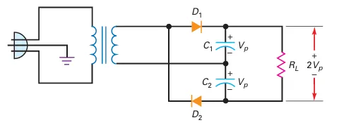
Advantages Over Half-Wave Designs:
Higher Ripple Frequency:
Output ripple frequency is 120 Hz, compared to 60 Hz in half-wave designs.
Easier to filter due to higher frequency, resulting in smoother DC output.
Diode Ratings:
Peak Inverse Voltage (PIV) rating of diodes only needs to exceed \(V_p\).
Allows use of diodes with lower voltage ratings, reducing cost and complexity.
Summary
Half-Wave Rectifier:
Diode in series with load resistor.
Output: Half-wave signal.
Average DC output: \(31.8\%\) of the peak voltage.
Transformer:
Step-down configuration: Voltage decreases, current increases.
Secondary voltage: \(V_{\text{secondary}} = \frac{V_{\text{primary}}}{\text{turns ratio}}\).
Full-Wave Rectifier:
Center-tapped transformer with two diodes.
Output: Full-wave signal with peak value = half of secondary voltage.
Average DC output: \(63.6\%\) of the peak voltage.
Ripple frequency: Double (120 Hz).
Bridge Rectifier:
Four diodes configuration.
Output: Full-wave signal with peak value = secondary voltage.
Average DC output: \(63.6\%\) of the peak voltage.
Ripple frequency: Double (120 Hz).
Choke-Input Filter:
LC voltage divider: \(X_L > X_C\).
Passes average value of rectified signal to load resistor.
Capacitor Input Filter:
Passes peak value of rectified signal to load resistor.
Ripple typically less than \(10\%\) of DC voltage.
Most widely used in power supplies.
Peak Inverse Voltage (PIV) and Surge Current:
PIV: Maximum voltage across non-conducting diode.
Surge Current: Brief large current when power is first turned on.
Clippers and Limiters:
Clippers: Shape signals by clipping positive/negative parts.
Limiters/Diode Clamps: Protect circuits from excessive input.
Clampers:
Shifts signal by adding a DC voltage.
Peak-to-peak detector produces load voltage equal to peak-to-peak value.
Voltage Multipliers:
Doubler: Output = \(2 \times\) peak value.
Tripler/Quadrupler: Multiply input peak by 3/4.
Used in high-voltage power supplies.