Introduction
Electronic systems such as HDTVs, audio amplifiers, and computers require a DC voltage to operate effectively.
Power-line voltage is alternating (AC) and typically too high, so it must be converted.
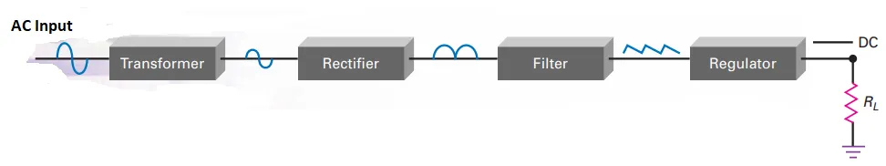
Key Components of a Power Supply
Voltage Reduction
Objective: Lower the high AC line voltage to a suitable level.
DC Conversion
Objective: Convert the reduced AC voltage to a constant DC output.
Power Supply Unit (PSU)
The section of the electronic system responsible for generating the DC voltage.
Includes various internal circuits for different functions.
Internal Circuits of a Power Supply
Rectifiers
Function: Allow current to flow in only one direction.
Purpose: Convert AC voltage to DC voltage.
Filters
Function: Smooth out fluctuations in the DC output.
Purpose: Ensure a steady and consistent DC voltage.
Voltage Regulators
Function: Maintain a constant DC output voltage despite variations in input or load conditions.
Other Circuits
Clippers: Modify the shape of the voltage waveform.
Clampers: Shift the voltage level of the waveform.
Voltage Multipliers: Increase the voltage to a higher level.
Summary
Explore the essential elements of power supplies, including rectifiers, filters, voltage regulators, clippers, clampers, and voltage multipliers.
Chapter Outline
The Half-Wave and Full-Wave Rectifier
The Choke and Capacitor Filter
Peak Inverse Voltage and Surge Current
Other Power-Supply Topics
Clippers and Limiters
Clampers
Voltage Multipliers
Half-Wave Rectifier Circuit
Figure shows a half-wave rectifier circuit with an AC source.
The AC source produces a sinusoidal voltage.
Positive Half-Cycle:
Forward-biases the diode.
As the switch is closed, the positive half-cycle appears across the load resistor \(\Rightarrow\) unidirectional load current.
Negative Half-Cycle:
Reverse-biases the diode.
The ideal diode acts as an open switch.
No voltage appears across the load resistor.

Half-Wave Rectifier Waveforms
Input voltage waveform is a sine wave with an instantaneous value of \(v_{in}\) and a peak value of \(V_p(\text{in})\).
A pure sinusoid has an average value of zero over one cycle.
Each instantaneous voltage has an equal and opposite voltage half a cycle later.
DC voltmeter reading: Zero (indicates average value).

Fig. (b): Diode conducts during positive half-cycles and does not conduct during negative half-cycles.
Fig. (c): The circuit clips off the negative half-cycles, producing a half-wave signal.
The half-wave voltage produces a unidirectional load current.
If the diode were reversed:
It would become forward-biased during the negative half-cycle.
Output pulses would be negative (Fig. (d)).
Characteristics of Half-Wave Signal
Fig. (c): The half-wave signal is a pulsating DC voltage.
Characteristics:
Increases to a maximum.
Decreases to zero.
Remains at zero during the negative half-cycle.
This is not the constant DC voltage needed for electronic equipment.
To obtain a constant voltage (like a battery), filtering of the half-wave signal is required (discussed later).
Troubleshooting and Ideal Diode
For troubleshooting, use the ideal diode to analyze a half-wave rectifier.
- Peak output voltage equals peak input voltage:\[\text{Ideal half-wave}:~V_p(\text{out}) = V_p(\text{in})\]
DC Value of a Half-Wave Signal
Definition: DC value = Average value of the signal.
- Formula:\[\text{DC Value (Half-Wave)} = \frac{V_p}{\pi}\]
- \[V_{DC} \approx 0.318 \, V_p\]
Approximation: - , then If Example:\[V_{DC} = 31.8 \text{ V}\]
RMS Value of a Half-Wave Signal
- RMS Formula:\[V_{rms} = 1.57 \, V_{avg}\]
- Average Value:\[V_{avg} = V_{DC} = 0.318 \, V_p\]
- Alternative Formula:\[V_{rms} = \frac{V_p}{\sqrt{2}} = 0.707V_p\]
Definition:
RMS value represents the DC value that produces the same heating effect as the AC waveform.
Output Frequency
- Same Frequency:\[f_{out} = f_{in}\]
Each input cycle produces one output cycle.
Second Approximation
Diode Forward Voltage:
Diode conducts when \(V_{in} > 0.7 \text{ V}\).- Adjusted Voltage:\[V_{p(out)} = V_{p(in)} - 0.7 \text{ V}\]
- , then If Example:\[V_{p(out)} \approx 4.3 \text{ V}\]
Half-wave rectifier LAB example
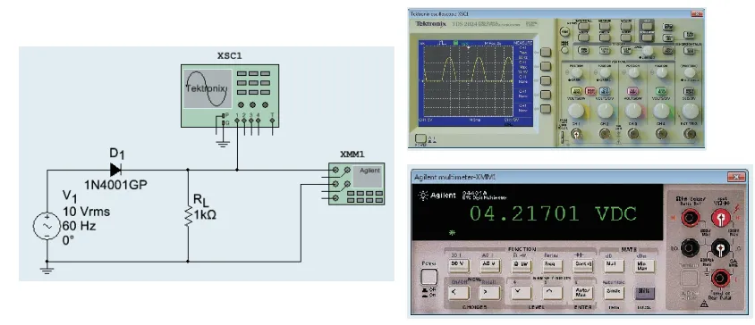
Source voltage \(\Rightarrow 10 \mathrm{~V}_{\mathrm{rms}}\Rightarrow\) calculate the peak ac source value .
- The rms value of a sine wave equals:\[V_{\text {rms }}=0.707 V_p\]
- The peak source voltage :\[V_p=\frac{V_{\text {rms }}}{0.707}=\frac{10 \mathrm{~V}}{0.707}=14.1 \mathrm{~V}\]
- With an ideal diode, the peak load voltage is:\[V_{p(\text { out })}=V_{p(\text { in })}=14.1 \mathrm{~V}\]
- The dc load voltage is:\[V_{\mathrm{dc}}=\frac{V_p}{\pi}=\frac{14.1 \mathrm{~V}}{\pi}=4.49 \mathrm{~V}\]
- With the second approximation, we get a peak load voltage of:\[V_{p(\text { out })}=V_{p(\text { in })}-0.7 \mathrm{~V}=14.1 \mathrm{~V}-0.7 \mathrm{~V}=13.4 \mathrm{~V}\]
- The dc load voltage:\[V_{\mathrm{dc}}=\frac{V_p}{\pi}=\frac{13.4 \mathrm{~V}}{\pi}=4.27 \mathrm{~V}\]
Transformers in Electronics
United States Nominal Line Voltage: \(120~\mathrm{V_{rms}}\) at 60 Hz
Actual voltage varies from \(105-125~ V_{rms}\).
Purpose of Transformer:
Steps down line voltage to safer levels for electronics.Prevents damage to circuits like diodes and transistors.
Transformer Basics:
Primary winding: Applies line voltage.
Secondary winding: Produces stepped-down voltage.
Turns Ratio Formula:

Phasing Dots:
Dotted ends have the same phase.
Positive half-cycle on primary = positive half-cycle on secondary.
If dots were on opposite ends, secondary voltage would be 180° out of phase.
Half-Wave Rectification:
Positive half-cycle: Diode forward biased.
Negative half-cycle: Diode reverse biased.
Result: Half-wave load voltage.
Step-Up/Step-Down:
Step-up: Secondary voltage \(>\) Primary voltage.
Step-down: Secondary voltage \(<\) Primary voltage.
Transformer example
