Circuit Configuration (Figure a)
Grounded center tap on secondary winding
Equivalent to two half-wave rectifiers
Each rectifier receives half the secondary voltage
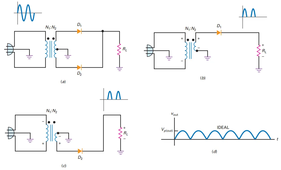
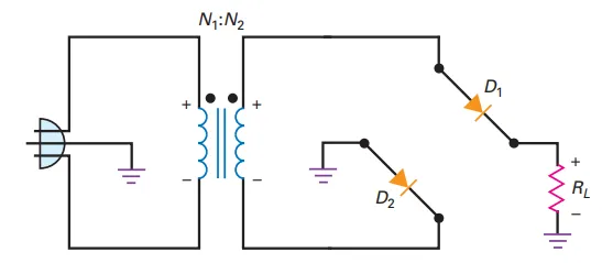
Operation
Diode D1: Conducts on positive half-cycle
Diode D2: Conducts on negative half-cycle
Rectified load current flows during both half-cycles
Positive Half-Cycle (Figure b)
D1 is forward biased
Positive load voltage across load resistor
Negative Half-Cycle (Figure c)
D2 is forward biased
Positive load voltage
Output Characteristics
Same load voltage polarity during both half-cycles
Load current direction remains constant
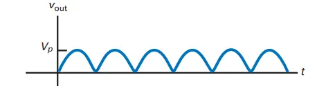
Converts AC input to pulsating DC output (Figure d)
DC or Average Value
- Full-wave rectifier average value:\[V_{\mathrm{dc}} = \frac{2 V_p}{\pi}\]
- Approximate form:\[V_{\mathrm{dc}} \approx 0.636 V_p\]
Example:
Peak voltage, \(V_p = 100\text{ V}\)
DC voltage: \(V_{\mathrm{dc}} \approx 63.6\text{ V}\)
Output Frequency
Half-wave rectifier: Output frequency = Input frequency
Full-wave rectifier: Output frequency is double the input frequency
Input frequency: \(f_{\text{in}} = 60\text{ Hz}\)
- Input period:\[T_{\text{in}} = \frac{1}{f_{\text{in}}} = \frac{1}{60\text{ Hz}} = 16.7\text{ ms}\]
- Output period:\[T_{\text{out}} = 0.5 \times T_{\text{in}} = 8.33\text{ ms}\]
- Output frequency:\[f_{\text{out}} = \frac{1}{T_{\text{out}}} = 120\text{ Hz}\]
- General relation:\[f_{\text{out}} = 2 f_{\text{in}}\]
Second Approximation
Full-wave rectifier \(\approx\) Two back-to-back half-wave rectifiers
- Approximate peak output voltage:\[V_{\text{peak,approx}} = V_p - 0.7\text{ V}\]
Example to illustrate the idea.
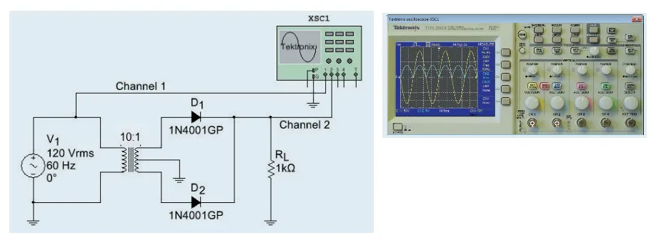
LAB example of full-wave rectifier
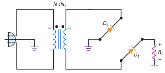
Bridge Rectifier Circuit
Produces a full-wave output voltage
Diodes D1 and D2 conduct on positive half-cycle
Diodes D3 and D4 conduct on negative half-cycle
Rectified load current flows during both half-cycles

Positive Half-Cycle
D1 and D2 are forward biased
Produces positive load voltage
Visualize D2 shorted: Circuit resembles half-wave rectifier
Negative Half-Cycle
D3 and D4 are forward biased
Produces positive load voltage
Visualize D3 shorted: Circuit resembles half-wave rectifier
Output Characteristics
Same load voltage polarity during both half-cycles
Load current direction remains constant
Converts AC input to pulsating DC output
Advantage: Uses entire secondary voltage
Average Value:
63.6% of peak value
Example: \(V_{\mathrm{dc}} = 63.6\text{ V}\) for \(V_p = 100\text{ V}\)
Output Frequency:
Example: \(f_{\mathrm{out}} = 120\text{ Hz}\) for \(f_{\mathrm{in}} = 60\text{ Hz}\)
Advantage:
Uses entire secondary voltage
Twice as much peak voltage and DC voltage compared to center-tap full-wave rectifier
Terminology:
Full-wave rectifier may refer to:
Conventional full-wave rectifier
Two-diode full-wave rectifier
Center-tapped full-wave rectifier
Peak Output Voltage:
Subtract 1.4 V (two diode drops) for accurate peak load voltage
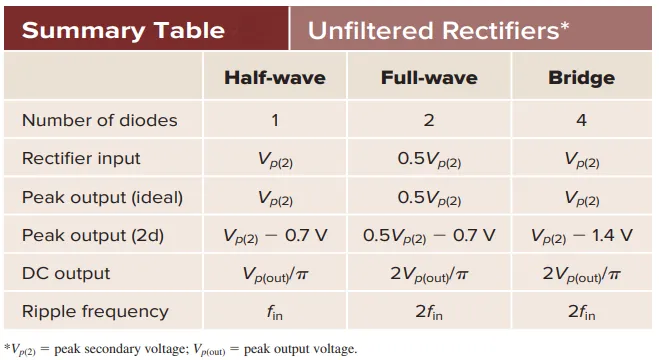
Summary Table: