The Oscillator
-
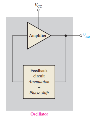
An oscillator is a circuit that generates a periodic waveform using only a DC supply voltage as input.
-
No repetitive input signal is required, except for synchronization in certain applications.
-
The output can be either:
-
Sinusoidal: e.g., sine wave.
-
Nonsinusoidal: e.g., square, sawtooth waves.
-
-
Two major types of oscillators:
-
Feedback Oscillators.
-
Relaxation Oscillators.
-

-
Feedback Oscillators:
-
Utilize positive feedback to return a fraction of the output signal to the input.
-
Maintain loop gain = 1, ensuring no net phase shift.
-
-
Relaxation Oscillators:
-
Use an \(RC\) timing circuit combined with a switching device (e.g., Schmitt Trigger).
-
Generate nonsinusoidal waveforms, typically square waves.
-
Feedback Oscillators
-
Based on positive feedback: A portion of the output is fed back in-phase to reinforce the signal.
-
Consist of an amplifier (e.g., transistor or op-amp) and a feedback circuit that provides phase shift and attenuation.
-
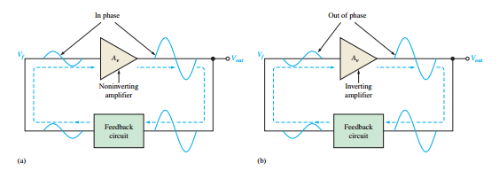
Conditions for oscillation:
-
Phase shift around the feedback loop must be \(0^\circ\).
-
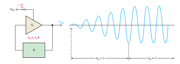
The closed-loop gain, \(A_{cl} = A_v B\), must equal 1.
-
-
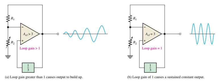
Initial condition for oscillation: The loop gain, \(A_v B\), must be greater than 1 to build up the output amplitude.
-
Once oscillation begins, the gain reduces to 1 to sustain stable oscillation without distortion.
-
The initial feedback signal typically originates from noise or power supply transients.
Oscillators with RC Feedback Circuits
-
Used for frequencies up to 1 MHz.
-
Common types include:
-
Wien-bridge oscillator
-
Phase-shift oscillator
-
Twin-T oscillator
-
-
Produce sinusoidal outputs using \(RC\) circuits in the feedback loop.
-
The Wien-bridge oscillator generates sine waves.
-
It uses an operational amplifier in a positive feedback configuration with a lead-lag network.
-
Theoretically developed by Max Wien in 1891.
-
Practical implementation achieved by William Hewlett in 1939.
-
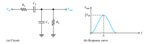
The Wien-bridge oscillator consists of two RC networks:
-
\(R_1\) and \(C_1\) form the lag portion.
-
\(R_2\) and \(C_2\) form the lead portion.
-
-
At low frequencies, the lead circuit dominates.
-
At high frequencies, the lag circuit dominates.
-
The circuit peaks at the resonant frequency, \(f_r\), with a phase shift of \(0^\circ\).
-
At resonant frequency, \(f_r\):
-
Phase shift = \(0^\circ\)
-
Attenuation, \(\frac{V_{out}}{V_{in}} = \frac{1}{3}\) (when \(R_1 = R_2\) and \(X_{C1} = X_{C2}\))
-
-
The resonant frequency formula is:
-
Below \(f_r\): output leads input.
-
Above \(f_r\): output lags input.
-
Lead-lag circuit in positive feedback loop.
-
Voltage divider in negative feedback loop.
-
Can be viewed as a noninverting amplifier configuration.
-
In the bridge configuration, the op-amp is connected across the lead-lag circuit and voltage divider.

-
Positive feedback requirements:
-
Phase shift around loop = \(0^\circ\) (achieved at \(f_r\))
-
Gain around loop = 1
-
-
Closed-loop gain must be 3 to offset 1/3 attenuation:

-
Initially need \(A_{cl} > 3\) to build up oscillation
-
Then gain must decrease to 3 to sustain oscillation
-
Methods to achieve this:
-
Zener diode arrangement
-
JFET as voltage-controlled resistor
-
-
Modified voltage divider with \(R_3\) and back-to-back zeners
-
Initially zeners appear as opens - higher gain
-
When output reaches zener voltage, zeners conduct - gain reduces to 3
-
Simple but can cause distortion

-
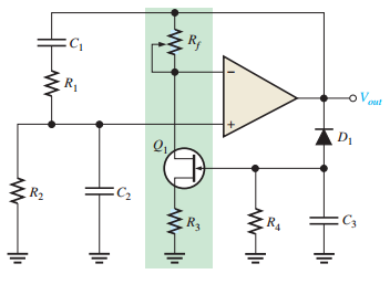
Better method using JFET as voltage-controlled resistor
-
JFET operates in ohmic region
-
Gate voltage controls drain-source resistance
-
Negative feedback automatically adjusts gain
-
Produces excellent sinusoidal waveform
-
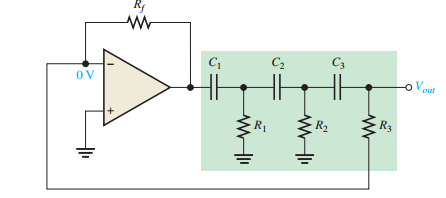
Uses three \(RC\) sections, each providing up to \(90^\circ\) phase shift (total \(180^\circ\)).
-
Op-amp inversion provides additional \(180^\circ\) for \(0^\circ\) net phase shift.
-
Attenuation: \(B = 1/29\), requiring amplifier gain \(A_v > 29\).
-
Frequency: \(f_r = \dfrac{1}{2 \pi \sqrt{6} R C}\).
-
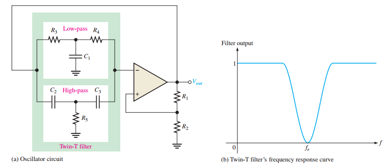
Uses two T-type \(RC\) filters (low-pass and high-pass) forming a band-stop response.
-
Oscillates at the center frequency (\(f_r\)) where negative feedback is minimal.
-
Positive feedback through a voltage divider enables oscillation.
Oscillators with LC Feedback Circuits
-
Suitable for frequencies above 1 MHz.
-
Use discrete transistors (BJT or FET) due to op-amp frequency limitations.
-
Types: Colpitts, Clapp, Hartley, Armstrong, and Crystal-Controlled oscillators.
-
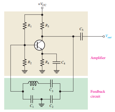
Uses an \(LC\) tank circuit with capacitors \(C_1\) and \(C_2\) and inductor \(L\).
-
Resonant frequency: \(f_r \approx \dfrac{1}{2 \pi \sqrt{L C_{\text{T}}}}\), where \(C_{\text{T}} = \dfrac{C_1 C_2}{C_1 + C_2}\).
-
Attenuation: \(B = C_2 / C_1\), requiring \(A_v > C_1 / C_2\) for start-up.
-
Loading reduces \(Q\), affecting \(f_r\).

-
A variation of Colpitts with an additional capacitor \(C_3\) in series with the inductor.
-
Total capacitance: \(C_{\text{T}} = \dfrac{1}{\dfrac{1}{C_1} + \dfrac{1}{C_2} + \dfrac{1}{C_3}}\).
-
If \(C_3 \ll C_1, C_2\), then \(f_r \approx \dfrac{1}{2 \pi \sqrt{L C_3}}\), improving frequency stability.
-
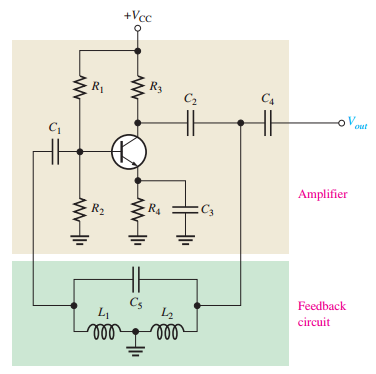
Uses two series inductors (\(L_1, L_2\)) and a parallel capacitor.
-
Frequency: \(f_r \approx \dfrac{1}{2 \pi \sqrt{L_{\text{T}} C}}\), where \(L_{\text{T}} = L_1 + L_2\).
-
Attenuation: \(B \approx L_1 / L_2\), requiring \(A_v > L_2 / L_1\) for start-up.
-
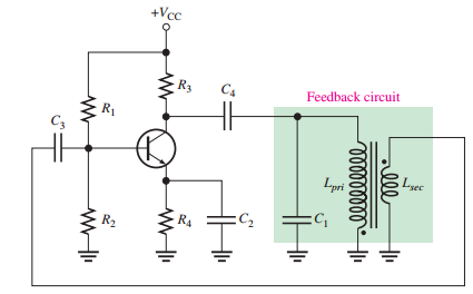
Uses transformer coupling ("tickler coil") for feedback.
-
Frequency: \(f_r = \dfrac{1}{2 \pi \sqrt{L_{\text{pri}} C_1}}\).
-
Less common due to transformer size and cost.
-
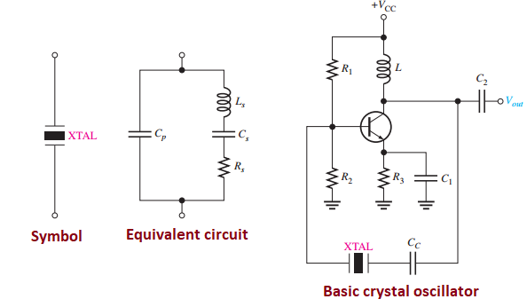
Use a piezoelectric quartz crystal for high stability and \(Q\) (several thousand).
-
Operates in series or parallel resonance modes.
-
The fundamental frequency is limited to 20 MHz, with higher frequencies utilizing overtone modes. These overtones are roughly integer multiples of the fundamental frequency.
Relaxation Oscillators
-
Use an \(RC\) timing circuit and a switching device to produce non-sinusoidal waveforms (e.g., triangular, sawtooth, square).
-
Common types of relaxation oscillators:
-
Triangular-wave oscillator
-
Sawtooth VCO (Voltage-Controlled Oscillator)
-
Square-wave oscillator
-
-
Uses an op-amp integrator and a comparator with hysteresis.
-
Output: Triangular wave from integrator, square wave from comparator.
-
Frequency: \(f_r = \dfrac{1}{4 R_1 C} \left( \dfrac{R_2}{R_3} \right)\).
-
UTP and LTP set by \(R_2\) and \(R_3\):

-
Uses an op-amp integrator and a Programmable Unijunction Transistor (PUT) switch.
-
Frequency: \(f = \dfrac{|V_{\text{IN}}|}{R_i C} \left( \dfrac{1}{V_p - V_{\text{F}}} \right)\).
-
PUT controls peak voltage, triggering capacitor discharge.

-
Uses an op-amp with an \(RC\) circuit and hysteresis.
-
Capacitor charges/discharges between feedback voltages, producing a square wave.

The 555 Timer as an Oscillator
-
Versatile IC with two comparators, a flip-flop, a discharge transistor, and a resistive voltage divider.
-
Used as an astable multivibrator (free-running oscillator) or VCO.

-
Produces a square-wave output.
-
Frequency: \(f_r = \dfrac{1.44}{(R_1 + 2 R_2) C_{\text{ext}}}\).
-
Duty cycle: \(\left( \dfrac{R_1 + R_2}{R_1 + 2 R_2} \right) 100\%\).
-
Diode addition allows duty cycles below 50%.

-
Control voltage on pin 5 varies threshold levels, changing frequency.
-
Frequency decreases with increasing control voltage.
-
Applications: Phase-locked loops for communication receivers.

-
Oscillators are essential for generating periodic signals in communication, digital, and test systems.
-
Feedback oscillators use positive feedback to generate sinusoidal outputs.
-
Relaxation oscillators produce nonsinusoidal waveforms using \(RC\) timing circuits.
-
\(LC\) oscillators and crystal-controlled oscillators are used for generating higher frequencies.
-
The 555 timer is a versatile IC used in astable and VCO (Voltage-Controlled Oscillator) applications.