Demonstrative Video
Contents:
-
Construction
-
Working Principle
-
EMF Equation
-
Transformation Ratio (K)
-
Rating of a Transformer
-
Losses in a Transformer
-
Ideal and Practical Transformers
-
Phasor Diagram of a Transformer on No Load
-
Phasor Diagram of a Transformer on Load
-
Equivalent Circuit
-
Voltage Regulation
-
Efficiency
-
Open Circuit (OC) Test and Short-Circuit (SC) Test
Introduction to Single-Phase Transformers
-
Static device which can transfer electrical energy from one circuit to another circuit without change of frequency .
-
\(V~\uparrow~\Rightarrow~I~\downarrow\) and vice versa
-
Works on the principle of mutual induction .
-
Works with ac voltage i.e. time varying.
-
A major application is to increase voltage before transmitting electrical energy over long distances through wires and to reduce voltage at places where it is to be used.
-
Used in electronic circuits to step down the supply voltage to a level suitable for the low-voltage circuits they contain.
-
Signal and audio transformers are used to couple stages of amplifiers and to match devices such as microphones to the input of amplifiers.
Construction
-
Mainly consists of two coils or windings placed on a common core.
-
With the increase in size (capacity) and operating voltage, it also needs other parts such as a suitable tank, bushing, conservator, breather, etc.
-
Two basic parts— core and windings will be discussed.
Transformer Core:
-
composition depends on voltage, current and frequency
-
core materials are soft iron and steel
-
Air-core transformers are used when the voltage source has a high frequency (above 20 kHz) and Iron-core when frequency is low (below 20 kHz).
-
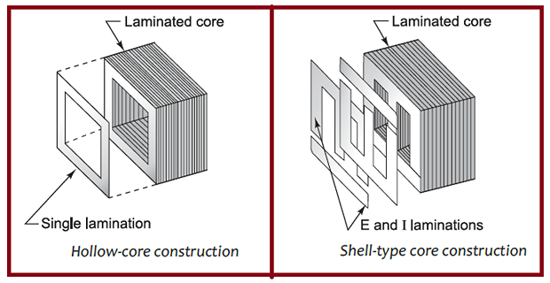
constructed of laminated steel to provide a continuous magnetic path
-
high-grade silicon steel is used where hysteresis loss is very low
-
alternating flux induced eddy currents in the core.
-
cause eddy current loss in the core
-
Silicon content in the steel increases its resistivity to eddy-current loss, thereby reducing eddy-current losses.
-
To reduce eddy-current losses further, the core is laminated by a light coat of varnish or by an oxide layer on the surface
-
two main shapes of cores used in laminated steel-core transformers
Transformer Windings:
-
Two coils, called windings, are wrapped around a core
-
primary winding in which electrical energy is fed
-
secondary winding which is connected to the load
-
Windings made up of an insulated copper conductor in the form of a round wire or strip
-
The windings are insulated from each other and the core, using cylinders of insulating material such as a press board or Bakelite
-
For simplicity, the primary and secondary windings are shown on separate limbs of the core.
-
If such an arrangement is used in actual practice, all the flux produced in the primary winding will not link with the secondary winding.
-
Some of the flux will leak out through the air known as leakage flux
-
leakage flux cause poor performance of the transformer.
-
Hence, to reduce leakage flux, the windings are placed together on the same limb in actual transformers
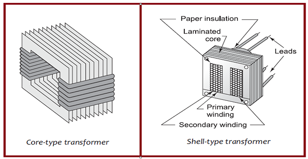
| Core-type | Shell-type | |
|---|---|---|
| 1. | magnetic frame with two limbs. | magnetic frame with three limbs. |
| 2. | single magnetic circuit | two magnetic circuits |
| 3. | winding encircles the core | core encircles most part of winding |
| 4. | cylindrical windings | sandwich-type windings |
| 5. | easy to repair | not easy to repair |
| 6. | better cooling as windings are uniformly distributed on two limbs | ineffective cooling as the windings are surrounded by the core |
| 7. | low-voltage transformers | high-voltage transformers |
Working Principle
-
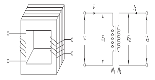
When an alternating voltage \(V_1\) is applied to a primary winding, an alternating current \(I_1\) flows in it producing an alternating flux in the core.
-
is induced in the primary winding. As per Faraday’s laws of electromagnetic induction, an emf\[e_{1}=-N_{1}{\frac{d\phi}{d t}}\]
-
Assuming leakage flux to be negligible, almost the whole flux produced in the primary winding links with the secondary winding.
-
is induced in the secondary winding. Hence, an emf\[e_{2}=-N_{2}{\frac{d\phi}{d t}}\]
-
Thus, energy transfer from primary to secondary winding
-
If \(N_2>N_1~\Rightarrow\) step-up transformer
-
If \(N_2<N_1~\Rightarrow\) called a step-down transformer
-
step-up transformer increase the voltage at the output, whereas a step-down transformer is used to decrease the voltage at the output.
EMF Equation
-
sinusoidally varying flux in the core alternating current flows in the winding sinusoidal alternating voltage Primary winding\[\phi = \phi_m\sin\omega t\]
-
is induced in the primary winding. As per Faraday’s laws of electromagnetic induction, an emf\[\begin{aligned} e_1& =-N_{1}\frac{d\phi}{d t} \\ &=-N_1\frac{d}{dt}(\phi_m\sin\omega t) \\ &=-N_1\phi_m\omega\cos\omega t \\ &=N_1\phi_m\omega\sin{(\omega t-90^{\circ})} \\ &=2\pi f\phi_m N_1\sin{(\omega t-90^{\circ})} \end{aligned}\]
-
Maximum value of induced emf \(=2\pi f\phi_m N_1\)
-
RMS value of induced emf in primary winding\[E_1=\frac{E_{\max}}{\sqrt{2}}=\boxed{\frac{2\pi f\phi_mN_1}{\sqrt{2}}=4.44f\phi_m N_1}\]
-
RMS value of induced emf in the secondary winding\[\begin{aligned} &\boxed{E_2 =4.44f\phi_m N_2 } \\ \text{Note:}~ \Rightarrow~&\boxed{\frac{E_{1}}{N_{1}} =\frac{E_2}{N_2}=4.44f\phi_m } \end{aligned}\]
-
Thus, emf per turn is same in primary and secondary windings
-
Also equal emf is induced in each turn of the primary and secondary windings.
Transformation ratio (K)
Rating of a Transformer
-
The rating of a transformer indicates the output power from it.
-
Load is not fixed and power factor continuously changes.
-
Rating is not expressed in terms of power but in terms of the product of voltage and current, known as the VA rating.
-
Rating is generally expressed in kilovolt-ampere (kVA).\[\text{kVA rating of a transformer} = \frac{V_{1}I_{1}}{1000}=\frac{V_{2}I_{2}}{1000}\]
-
We can calculate full-load currents of primary and secondary windings from kVA rating of a transformer.
-
Full-load current is the maximum current which can flow through the winding without damaging it.\[\begin{aligned} \text{Full-load primary current}~ I_1 & =\frac{\mathrm{kVA rating}\times1000}{V_1}\\ \text{Full-load secondary current}~ I_2 & =\frac{\mathrm{kVA~rating}\times1000}{V_2} \end{aligned}\]