Demonstrative Video
ELECTROMECHANICAL ENERGY CONVERSION
-
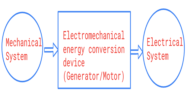
A device (machine) that converts energy from electrical to mechanical form or from mechanical to electrical form is called an electro-mechanical energy conversion device .
-
A DC machine (generator or motor) is an electromechanical energy conversion device.
-
DC Generator: convert mechanical power ( \(T\omega\) ) into DC electrical power ( \(EI\) )
-
DC Motor: convert electrical power into mechanical power
-
The same electromechanical device is capable of operating either as a motor or generator depending upon whether the input power.
-
Thus, the motor and generator actions are reversible.
-
The electro-mechanical energy conversion takes place through magnetic field.
-
In power plants (hydroelectric, steam, diesel, nuclear, etc.), generators are used to convert various natural sources of energy into mechanical energy, which is then converted into electrical energy by generators.
-
Electric motors are used to power industrial machinery, such as hammer presses, drilling machines, lathes, shapers, furnace blowers, etc., as well as household appliances, such as refrigerators, fans, water pumps, toys, mixers, etc.
Construction of DC Machines
-
A dc machine essentially consists of the following main parts:
-
Field windings
-
Armature core and armature windings
-
Commutator
-
Brushes
-
Field Windings:
-
mounted on the pole core and they produce alternate north and south poles
-
form an electromagnet which provides the main magnetic field
-
current flows through filed windings to produce magnetic flux
-
generally made of copper wire

Armature Core and Armature Windings
-
mounted on a shaft and rotates in the magnetic field.
-
The armature core is made of laminations of sheet steel.
-
The outer surface of the core is cylindrical in shape.
-
Provided with a large number of slots into which the armature conductors are placed.
-
The ends of the armature windings are brought to the commutator segments
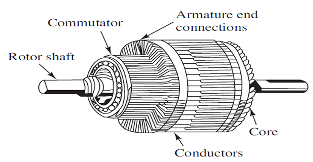
Commutator
-
used for collecting current from the armature conductors.
-
made of a number of wedge-shaped segments of copper.
-
segments are insulated from each other by thin layers of mica.
-
each commutator segment is connected to the armature conductor.
-
converts the ac current induced in the armature conductors into unidirectional current across the brushes
Brushes
-
collect current from commutator and supply to the external circuit.
-
usually made of carbon.
Types of Armature
Winding
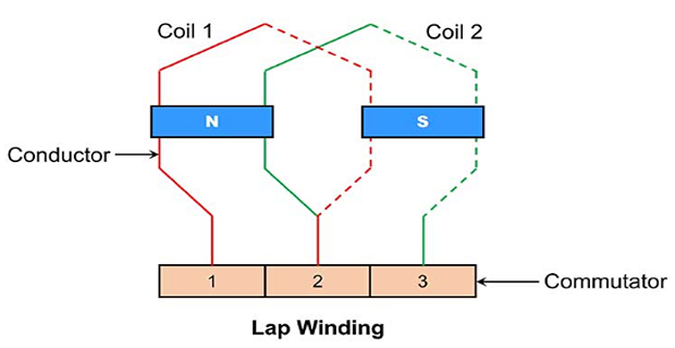
Depending upon the manner in which the armature conductors are connected
to the commutator segments, there are the two types of armature
winding:
-
Lap winding
-
armature conductors are connected in series through commutator segments in such a way that the armature winding is divided into as many parallel paths as the number of poles.
-
If there are Z conductors and P poles, there will be P parallel paths, each containing Z/P conductors in series.
-
The total emf is equal to the emf generated in any one of the parallel paths.
-
The total armature current divides equally among the different parallel paths.
-
It is used in low-voltage high-current machines .
-
-
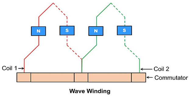
Wave winding
-
the armature conductors are connected in series through commutator segments in such a way that the armature winding is divided into two parallel paths irrespective of the number of poles.
-
If there are Z conductors, Z/2 conductors will be in series in each parallel path.
-
The total emf is equal to the emf generated in any one of the parallel paths.
-
The total armature current divides equally between two parallel paths.
-
It is used in high-voltage low-current machines .
-
Classification of Machines
-
Depending upon the method of excitation of field winding, dc machines are classified into two classes:
-
Separately excited machines: the field winding is provided with a separate dc source to supply the field current
-
Self-excited machines: no separate source is provided to drive the field current, but the field current is driven by its own emf generated across the armature terminals when the machine works as a generator.
-
-
Self-excited machines are further classified into three types, depending the way field winding is connected to the armature.
-
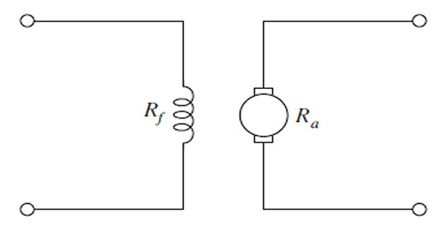
Shunt-wound machines
-
Series-wound machines
-
Compound-wound machines
-
-
Shunt-wound machines
-
field winding is connected in parallel with the armature.
-
number of turns of the field winding may range from 300 to 1000

-
-
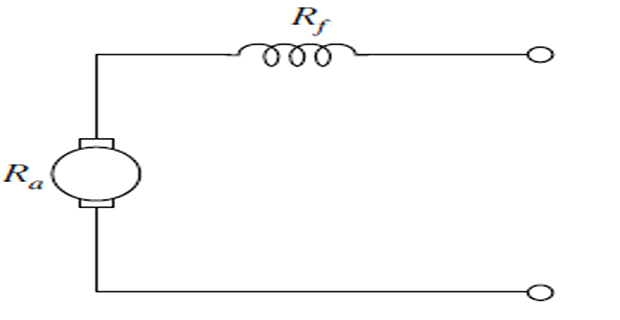
Series-wound machines
-
field winding is connected in series with the armature
-
Number of turns of the field winding is small (2 to 10 turns)
-
field winding will have a heavy area of cross-section to carry the large armature current.
-
-
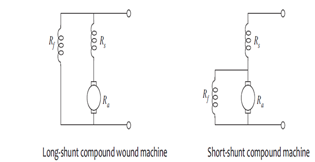
Compound-wound machines
-
carry both the shunt and series field windings.
-
further classified into long shunt and short shunt , depending upon the direction of current flow in the two types of field windings
-
Both the shunt field winding and the series field winding are generally wound on the same pole.
-
EMF Equation
-
When the armature completes one revolution, each conductor cuts the magnetic flux.
-
Therefore, flux cut by one conductor in one revolution of the armature\[\begin{aligned} & =\text { Flux per pole } \times \text { Number of poles } \\ & =\phi P \text { webers } \end{aligned}\]
-
Time taken to complete one revolution \(=\frac{60}{N}\) seconds.
-
Hence, average emf induced in one conductor\[\begin{aligned} & =\frac{\text { Flux cut }}{\text { Time taken }}=\frac{\phi P}{60 / N} =\frac{\phi P N}{60} \text { volts } \end{aligned}\]
-
Induced emf\[\begin{aligned} E= & \text { Resultant emf per parallel path } \\ = & \text { Average emf per conductor } \times \text { No. of conductors in series per } \\ & \text { parallel path } \\ = & \frac{\phi P N}{60} \times \frac{Z}{A} \\ &\boxed{E = \frac{\phi Z N}{60} \frac{P}{A}~ \text { volts }} \end{aligned}\]
-
In case of a dc generator, this emf is called generated emf \(\left(E_g\right)\) .
-
For a dc motor, the induced emf opposes the applied emf and hence, it is called back emf \(\left(E_b\right)\) .
Voltage–Current relationships
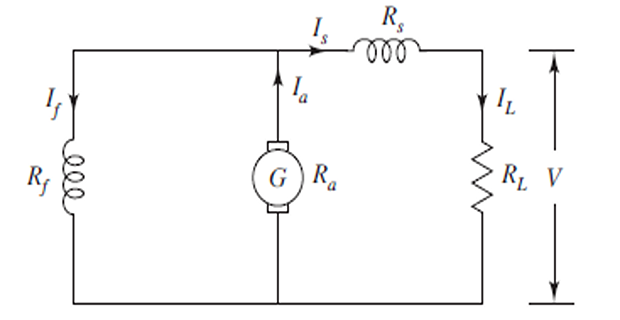
Generator:
-
When the machine runs as a generator, the generated emf ( \(E_g\) ) must be sufficient to supply both the terminal voltage ( \(V\) ) and the internal voltage drop.
Applications:
-
Ordinary lighting and power supply
-
Charging batteries
Applications:
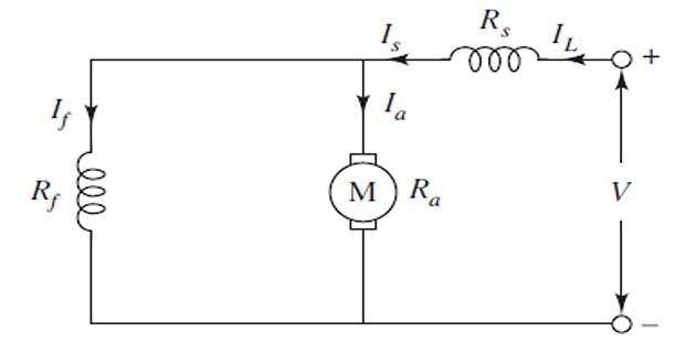
-
As boosters in distribution systems
Compound generator
Applications:
-
Lamp loads
-
Heavy power service such as electric railways
-
Arc welding
Motor:
-
When the dc machine runs as a motor, the applied voltage \(V\) across its terminals must be sufficient to overcome the back emf \(E_b\) and supply the internal voltage drop.
Applications:
-
For driving lathes
-
Centrifugal pumps
-
Blowers and fans
Applications:
-
Electric locomotives
-
Cranes and hoists
-
Conveyors
Compound motor
Applications:
-
Elevators
-
Conveyors
-
Rolling mills
-
Air compressors