Set 23 — Three-Phase Transformers and Connections
Nothing in a three-phase transformer is new. Each limb carries one primary winding and one secondary winding, and between that pair the e.m.f. equation, the turns ratio and the equivalent circuit of Sets 15 to 21 apply unchanged. What is new is bookkeeping: the nameplate quotes line voltages and a total kVA, while the windings live at phase voltages and phase currents, and the delta or star connection sets the factor of \(\sqrt{3}\) between them.
Every problem here is therefore worked the same way — convert the terminal data to per-phase quantities, do the transformer calculation on one phase, and convert back to line quantities at the very end. The set runs from pure current bookkeeping through efficiency to regulation, and the arithmetic trap in all five is the same: using a line quantity where the winding sees a phase quantity.
The nameplate is in line quantities and total volt-amperes. A "500 kVA, 6000 V/400 V" transformer handles 500 kVA in total across three phases, and both voltages are line-to-line. The same holds for a load quoted in kW.
\[ S = \sqrt{3}\,V_L I_L, \qquad P = \sqrt{3}\,V_L I_L\cos\phi \]The connection converts line to winding. Every per-phase result must be pushed through these two lines before it can be quoted at the terminals:
\[ \text{star: } V_L = \sqrt{3}\,V_{ph},\; I_L = I_{ph} \qquad \text{delta: } V_L = V_{ph},\; I_L = \sqrt{3}\,I_{ph} \]The transformation ratio is a per-phase ratio, equal to the turns ratio of the two windings on one limb. The ratio of the line voltages is that number multiplied or divided by \(\sqrt{3}\) depending on the connection:
\[ K = \frac{N_2}{N_1} = \frac{V_{2,ph}}{V_{1,ph}} \qquad\text{(for }\Delta/Y:\; \frac{V_{2L}}{V_{1L}} = \sqrt{3}\,K\text{)} \]Referred quantities are referred per phase, exactly as in Set 18. With everything brought to the secondary winding of one limb:
\[ R_{02} = R_2 + K^2R_1, \qquad X_{02} = X_2 + K^2X_1 \]Losses are three times the per-phase loss. Iron loss is quoted for the whole transformer and is constant; copper loss scales with the square of the loading fraction \(x\):
\[ P_{cu} = 3I_{2,ph}^2R_{02}, \qquad \eta = \frac{xS\cos\phi}{xS\cos\phi + P_i + x^2P_{cu}} \]Regulation is computed on one phase and quoted as a percentage, so it transfers unchanged to line quantities and to the other side of the transformer:
\[ \Delta V = I_2\left(R_{02}\cos\phi + X_{02}\sin\phi\right), \qquad \%\text{regn} = \frac{\Delta V}{E_{2,ph}}\times100 \]A percentage impedance is a per-phase percentage. "7% impedance" means the full-load current produces a drop of 7% of the rated phase voltage across \(Z_{02}\).
A 3-phase, 500 kVA, 6000 V/400 V, 50 Hz, delta-star connected transformer delivers 300 kW at 0.8 power factor lagging to a balanced three-phase load on the LV side, the HV side being supplied from a 6000 V three-phase system. Assuming the transformer to be ideal, calculate
- the line and winding currents on the LV side
- the line and winding currents on the HV side.
Read the nameplate before touching a number. This is a single three-phase unit, not a bank of three single-phase transformers, and four conventions are being used at once: 500 kVA is the total rating, 6000 V and 400 V are line-to-line voltages, the 300 kW is the total power absorbed by the load, and the 0.8 power factor is the load's. Nothing on the plate refers to a single winding.

Convert the load to volt-amperes, because currents follow from kVA and not from kW:
The transformer is ideal, so the input kVA is the same 375 kVA — the machine is running at 75% of its 500 kVA rating.
LV side. The line current comes from the total kVA and the line voltage:
The secondary is in star, so each winding carries the line current: \(I_{2,ph} = I_{2L} = 541.3\ \text{A}\).
HV side. The same 375 kVA at 6000 V gives the line current, and the delta connection then splits it:
Check the two winding currents against the turns ratio. One limb carries an HV winding at the full 6000 V and an LV winding at \(400/\sqrt3 = 230.9\) V, so the per-phase ratio is
Winding currents are in the inverse turns ratio; line currents are not, because the two sides are connected differently. Here the line-current ratio is only \(541.3/36.08 = 15.0 = 25.98/\sqrt{3}\).
A 3-phase, 50 Hz transformer has a delta-connected primary and a star-connected secondary, the line voltages being 22,000 V and 400 V respectively. The secondary supplies a star-connected balanced load at 0.8 power factor lagging, and the line current on the primary side is 5 A. Determine
- the current in each coil of the primary
- the current in each secondary line
- the output of the transformer in kW.
Get the phase voltages first. The primary is in delta, so each primary coil is across the full line voltage; the secondary is in star, so each secondary coil carries only \(1/\sqrt3\) of its line voltage:
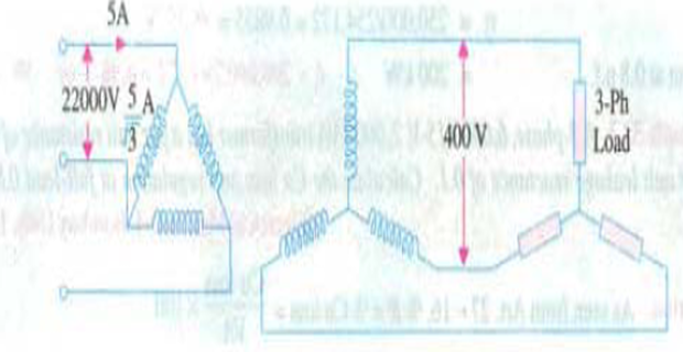
The transformation ratio belongs to one limb, so it is the ratio of the two phase voltages, not of the two line voltages:
The line-voltage ratio is \(22{,}000/400 = 55\). The winding ratio is \(55\sqrt3 = 95.26\), and it is the winding ratio that transforms current.
Primary coil current, from the delta rule:
Secondary coil current, from the m.m.f. balance on that limb:
The secondary is in star, so each secondary line also carries 275 A.
The output, from the secondary line quantities:
Check on the primary side, where the transformer being ideal means the same power enters: \(\sqrt3\times22{,}000\times5\times0.8 = 152.4\ \text{kW}\ \checkmark\)
A 500 kVA, 3-phase, 50 Hz transformer has a line-voltage ratio of 33/11 kV and is delta/star connected. The resistances per phase are: high voltage 35 Ω, low voltage 0.876 Ω, and the iron loss is 3050 W. Calculate the efficiency at full load and at one-half of full load
- at unity power factor
- at 0.8 power factor.
Per-phase voltages and the transformation ratio. The HV winding is in delta and sees 33 kV; the LV winding is in star and sees \(11/\sqrt3\) kV:
Refer the primary resistance to the secondary, one limb at a time:
Rated secondary current. The secondary is in star, so the phase current equals the line current:
Full-load copper loss is three times the per-phase loss:
Worth checking against the two windings taken separately. The HV delta coils carry \(8.748/\sqrt3 = 5.05\) A, so \(3(5.05)^2(35) = 2678\ \text{W}\) and \(3(26.24)^2(0.876) = 1810\ \text{W}\), totalling 4488 W. The referred figure is not an approximation.
Full-load efficiency. Total loss is \(3050 + 4488 = 7538\) W, and only the output changes with power factor:
Half load. The copper loss falls with the square of the loading, the iron loss does not fall at all:
The four results together show which variable moves the efficiency and which does not:
| Loading | Output at upf | Total loss | η at upf | η at 0.8 pf |
|---|---|---|---|---|
| Full load | 500 kW | 7538 W | 98.51% | 98.15% |
| Half load | 250 kW | 4172 W | 98.36% | 97.96% |
Halving the load more than halves the copper loss but leaves the iron loss untouched, so the efficiency barely moves. Dropping the power factor to 0.8 costs about four times as much efficiency as halving the load, because it reduces the output without reducing a single loss.
A 3-phase, 33/6.6 kV, delta-star, 2 MVA transformer has a primary resistance of 8 Ω per phase and a secondary resistance of 0.08 Ω per phase. The percentage impedance is 7%. Calculate the secondary terminal voltage with rated primary voltage applied, and hence the regulation, for full load at 0.75 power factor lagging.
Full-load secondary current. The secondary is in star, so the winding carries the line current:
Per-phase transformation ratio and referred resistance. The delta primary sees 33 kV per winding, the star secondary \(6.6/\sqrt3 = 3.81\) kV:
Note \(K^2 = 1/8.66^2 = 1/75\) exactly, so the 8 Ω primary winding contributes only 0.107 Ω on the low-voltage side.
The percentage impedance fixes \(Z_{02}\). Seven per cent of the rated phase voltage is the drop that full-load current produces across the equivalent impedance:
The impedance is almost entirely reactance — the resistance is only 12% of it — which is typical of a transformer of this size and is what makes the power factor matter so much below.
The approximate voltage drop at 0.75 lagging, for which \(\sin\phi = 0.661\):
Of the 199.6 V, the reactance contributes 175 × 1.000 = 175 V and the resistance only 24.5 V.
The terminal voltage, per phase and then per line:
The regulation is the same number expressed as a fraction:
Because it is a ratio, it can equally be read off the line voltages: \((6600-6254)/6600 = 5.24\%\). The \(\sqrt3\) cancels.
A 5000 kVA, 3-phase, 6.6/33 kV, delta-star transformer has a no-load loss of 15 kW and a full-load loss of 50 kW. The impedance drop at full load is 7%. Calculate the primary voltage required when a load of 3200 kW at 0.8 power factor is to be delivered at 33 kV.
Full-load secondary current. The 33 kV side is the star-connected secondary, so its winding current is the line current:
Equivalent impedance from the percentage figure, taken on the phase voltage \(33/\sqrt3 = 19.05\) kV:
Separate \(R_{02}\) from the loss data. The no-load loss is the iron loss and the full-load loss contains both, so the full-load copper loss is the difference:
The actual load is not full load. 3200 kW at 0.8 power factor is 4000 kVA, that is 80% of rating:
Confirming the 80%: \(70/87.5 = 0.80\). The drop and the regulation must be computed at this current, not at full-load current.
The drop per phase and the regulation at 0.8 lagging, \(\sin\phi = 0.6\):
Raise the primary by the same percentage. The secondary terminal voltage is to be held at 33 kV, so the applied primary voltage must exceed its rated value by the regulation:
The regulation is a pure ratio, so it applies to the 6.6 kV line voltage of the delta primary without any \(\sqrt3\) correction.
Key Formulas
| Quantity | Relation | Notes |
|---|---|---|
| Three-phase kVA | \(S = \sqrt{3}\,V_LI_L\) | Total, not per phase — Problems 1, 3 |
| Three-phase power | \(P = \sqrt{3}\,V_LI_L\cos\phi\) | Output in Problem 2 |
| Star connection | \(V_L = \sqrt{3}V_{ph},\; I_L = I_{ph}\) | LV side of Problems 1, 3–5 |
| Delta connection | \(V_L = V_{ph},\; I_L = \sqrt{3}I_{ph}\) | HV side of Problems 1, 2 |
| Transformation ratio | \(K = N_2/N_1 = V_{2,ph}/V_{1,ph}\) | Per limb — Problem 2 |
| Line ratio, \(\Delta/Y\) | \(V_{2L}/V_{1L} = \sqrt{3}K\) | Connection changes the terminal ratio |
| Referred resistance | \(R_{02} = R_2 + K^2R_1\) | Per phase — Problems 3, 4 |
| Copper loss | \(P_{cu} = 3I_{2,ph}^2R_{02}\) | Factor 3 for three limbs — Problem 3 |
| Loss at part load | \(P_{cu}(x) = x^2P_{cu,\text{FL}}\), \(P_i\) constant | Half load: quarter copper loss |
| Efficiency | \(\eta = \dfrac{xS\cos\phi}{xS\cos\phi + P_i + x^2P_{cu}}\) | Problem 3 |
| Copper loss from tests | \(P_{cu} = P_{\text{FL loss}} - P_{\text{no-load}}\) | Problem 5 |
| Percentage impedance | \(I_{2,\text{FL}}Z_{02} = \dfrac{\%Z}{100}\,V_{2,ph}\) | Phase voltage — Problems 4, 5 |
| Approximate drop | \(\Delta V = I_2(R_{02}\cos\phi + X_{02}\sin\phi)\) | Per phase — Problems 4, 5 |
| Regulation | \(\%\text{regn} = \dfrac{\Delta V}{E_{2,ph}}\times100\) | Ratio, so line or phase gives the same |
Common Mistakes
Treating the nameplate kVA as per phase. A 500 kVA three-phase transformer handles 500 kVA in total, so each limb handles 167 kVA. Dividing at the wrong point makes every current wrong by three — Problems 1 and 3.
Using the line-voltage ratio as the turns ratio. For the \(\Delta/Y\) transformer of Problem 2 the line ratio is 55 but the winding ratio is \(55\sqrt3 = 95.26\); only the winding ratio transforms current.
Forgetting that a delta winding carries \(I_L/\sqrt3\). The HV coil current in Problem 1 is 20.83 A, not the 36.08 A that flows in the supply line.
Applying \(\sqrt3\) to the star winding current. In star the coil is the line, so \(I_{ph} = I_L\) — the \(\sqrt3\) belongs to the voltage on that side — Problems 1, 4 and 5.
Referring a resistance with the line ratio. \(K^2\) in \(R_{02} = R_2 + K^2R_1\) is the square of the phase ratio: 1/27 in Problem 3 and 1/75 in Problem 4, not \((1/3)^2\) or \((1/5)^2\).
Taking the percentage impedance on the line voltage. Seven per cent of 6.6 kV is not the drop; it is 7% of \(6.6/\sqrt3 = 3.81\) kV — Problem 4.
Computing currents from kW instead of kVA. A 300 kW load at 0.8 power factor draws the current of a 375 kVA load; the power factor must be divided out first — Problem 1.
Scaling the iron loss with the load. Only the copper loss falls at half load, and it falls by four; the iron loss is fixed by the applied voltage — Problem 3.
Using full-load current for a part-load regulation. The 3200 kW load in Problem 5 draws 70 A, not 87.5 A, and the drop is 80% of the full-load figure.
Adding the \(\sqrt3\) back into a percentage. Regulation is dimensionless, so the same 3.79% applies to the phase voltage, the line voltage and the primary side alike — Problem 5.
Five problems, one habit: reduce the terminal data to a single limb, work the transformer theory of Sets 15 to 21 on that limb, then rebuild the line quantities. The connection never changes the physics of a winding — it only changes which \(\sqrt3\) stands between the winding and the terminal.
The repeated conversions are also an argument for a better set of units. If every voltage, current, impedance and power were expressed as a fraction of a chosen base, the \(\sqrt3\) factors would cancel once and for all, the percentage impedance would become the impedance, and a delta winding and a star winding would look identical on paper. That is exactly what the per-unit system does.
Next: Set 24 — Per-Unit System and Instrument Transformers, where base quantities absorb the connection factors and the current and potential transformers used for measurement are treated in their own right.