Set 29 — No-Load and Blocked-Rotor Testing
The six parameters of the equivalent circuit are not on the nameplate and cannot be computed reliably from the winding drawing. They are measured, by three tests chosen so that in each one a different part of the circuit dominates and the rest can be ignored: a DC measurement for the stator resistance, a run at rated voltage with the shaft free for the shunt branch, and a run at reduced voltage with the rotor clamped for the series branch.
This set works those tests both ways. Three problems extract parameters from readings — including the frequency correction that a reduced-frequency blocked-rotor test demands, and the design-class convention that divides a leakage reactance the tests cannot separate. Two more use a voltage sweep to split the no-load loss into core loss and windage, and then feed the whole parameter set back into the circuit to predict full-load current, torque and efficiency for a machine that was never loaded.
Three tests, three parts of the circuit. The DC test isolates \(R_1\), the no-load test isolates the shunt branch, and the blocked-rotor test isolates the series branch — because in each the other parts are either absent or negligible.
DC test. Apply direct current between two line terminals and read the voltage. No rotation, no reactance, no rotor current:
\[ R_1 = \frac{V_{DC}}{2I_{DC}}\ \text{(star)}, \qquad R_1 = \frac{3V_{DC}}{2I_{DC}}\ \text{(delta)} \]Two windings in series are being measured in star, so the per-phase value is half the reading.
No-load test at rated voltage. The slip is nearly zero, so \(R_2'/s\) is enormous and the rotor branch carries almost nothing; what remains is the exciting branch:
\[ \cos\phi_0 = \frac{P_0}{\sqrt3V_LI_0},\quad I_w = I_0\cos\phi_0,\quad I_\mu = I_0\sin\phi_0,\quad R_0 = \frac{V_{ph}}{I_w},\quad X_0 = \frac{V_{ph}}{I_\mu} \]Also \(|Z_{nl}| = V_{ph}/I_0 \approx X_1+X_m\), which is how \(X_m\) is separated once \(X_1\) is known.
Blocked-rotor test at reduced voltage, rotor held still. Now \(s = 1\), the rotor branch is a low impedance and the exciting branch may be ignored:
\[ |Z_{01}| = \frac{V_{ph}}{I},\quad R_{01} = \frac{P_{BR}}{3I^2} = R_1+R_2',\quad X_{01} = \sqrt{|Z_{01}|^2-R_{01}^2} \]Correct the reactance for test frequency, never the resistance. If the blocked-rotor test is run at \(f_{test}\) to keep the rotor resistance free of deep-bar effects:
\[ X_{01}\big|_{f_{rated}} = \frac{f_{rated}}{f_{test}}\,X_{01}\big|_{f_{test}} \]Divide the leakage reactance by design class. The tests give only the sum \(X_1+X_2'\); the split is a convention:
\[ \text{Class A, D and wound rotor: } X_1 = X_2' = 0.5X_{01}; \qquad \text{Class B: } X_1 = 0.4X_{01},\ X_2' = 0.6X_{01} \]The no-load input is not all core loss. It is stator copper loss plus core loss plus friction and windage. Running the no-load test at several voltages and extrapolating to zero voltage separates the last of these, since core loss vanishes with \(V^2\) while friction and windage does not.
The following tests were made on a 400 V, 50 Hz, 4-pole, 3-phase star-connected induction motor of rated current 20 A. All readings are of line quantities and total three-phase power.
| Test | Voltage | Current | Power |
|---|---|---|---|
| No load | 400 V | 5.0 A | 520 W |
| Blocked rotor | 83 V | 20.0 A | 1140 W |
A DC measurement gives a stator resistance of 0.55 Ω per phase. Determine
- the parameters of the exciting branch, \(R_0\) and \(X_0\)
- the total equivalent resistance and leakage reactance, and hence \(R_2'\), \(X_1\) and \(X_2'\)
- the current the machine would draw if switched directly on to 400 V at standstill.
The no-load test first. Take the phase voltage and find the no-load power factor from the three-phase power:
A power factor of 0.15 means \(\phi_0 = 81.4^\circ\) — the current is almost entirely magnetising, exactly as it must be when the shaft is doing no work.
Resolve the no-load current into its two components:
Note what \(R_0\) actually represents here: the whole 520 W of no-load input, which is core loss plus friction and windage plus the 41 W of no-load stator copper loss. Problem 5 separates those three; for the exciting branch alone the lumped value is the conventional answer.
Now the blocked-rotor test. With the rotor held, \(s=1\) and the rotor branch is a low impedance, so the exciting branch may be dropped:
The blocked-rotor power factor is \(1140/(\sqrt3\times83\times20) = 0.396\) — poor, because at standstill the leakage reactance dominates.
Separate resistance from reactance by the impedance triangle:
The equal split is the convention for a wound-rotor or Class A machine; Problem 4 examines what happens when it is not appropriate.
The magnetising reactance follows once \(X_1\) is known, because the no-load impedance is very nearly the series sum \(X_1+X_m\):
The shunt-model value \(X_0 = 46.72\ \Omega\) and the series-model value \(|Z_{nl}| = 46.19\ \Omega\) differ by 1%, which is the price of the very low no-load power factor; the series value is the one to pair with \(X_1\).
The direct-on-line starting current. The blocked-rotor impedance is the standstill impedance, so it need only be scaled to full voltage:
Equivalently, scale the test current in the ratio of the voltages: \(20\times400/83 = 96.4\ \text{A}\) — the same number, and the quicker route in an examination.
The completed parameter set:
| Parameter | Value | Test that fixed it |
|---|---|---|
| \(R_1\) | 0.550 Ω | DC |
| \(R_2'\) | 0.400 Ω | Blocked rotor, minus DC |
| \(X_1 = X_2'\) | 1.100 Ω | Blocked rotor, split by convention |
| \(R_0\) | 307.7 Ω | No load |
| \(X_0\) | 46.72 Ω | No load |
| \(X_m\) | 45.09 Ω | No load, minus \(X_1\) |
A 415 V, 50 Hz, 6-pole, 3-phase star-connected induction motor of rated current 30 A is tested with the rotor locked. To keep the rotor current distribution the same as it would be at the small slip frequency of normal running, the test is performed at 12.5 Hz. The readings are 44 V between lines, 30 A and 2020 W. A DC test gives a stator resistance of 0.4 Ω per phase. Determine
- the equivalent resistance and the referred rotor resistance
- the total leakage reactance at 50 Hz, and \(X_1\) and \(X_2'\)
- the direct-on-line starting current and starting torque at 415 V
- what would have been predicted had the test reactance been used uncorrected.
Why the test is run at reduced frequency at all. At standstill the rotor frequency equals the supply frequency, and in a deep-bar or double-cage rotor the current then crowds into the top of the bar, raising the apparent resistance well above its running value. Testing at a quarter of rated frequency puts the rotor current where it sits in normal service, at a slip frequency of a few hertz.
Reduce the readings to per-phase quantities:
The rotor resistance, which needs no frequency correction because resistance is not a function of frequency:
The reactance at test frequency, from the impedance triangle:
Scale it to rated frequency. Reactance is proportional to frequency, so the correction is a simple ratio:
This is the only quantity in the test that changes with frequency. The measured power, and therefore \(R_{01}\), is used exactly as read.
Direct-on-line starting current, using the corrected impedance at rated voltage:
The starting torque is the air-gap power at \(s=1\) divided by synchronous speed:
What the uncorrected figure would have given. Using \(X = 0.397\ \Omega\) instead of 1.586 Ω:
| Quantity | Corrected (50 Hz) | Uncorrected (12.5 Hz value) | Error |
|---|---|---|---|
| \(X_{01}\) | 1.586 Ω | 0.397 Ω | −75% |
| \(|Z_{01}|\) | 1.754 Ω | 0.847 Ω | −52% |
| \(I_{st}\) | 136.6 A | 283 A | +107% |
A predicted starting current more than twice the true value — enough to specify a starter, a cable and a protective device that are all wrong. The frequency correction is not a refinement.
The following test data were taken on a 7.5 hp, 4-pole, 208 V, 60 Hz, Y-connected induction motor having a rated current of 28 A.
DC test: \(V_{DC} = 13.6\ \text{V}\), \(I_{DC} = 28.0\ \text{A}\).
| Reading | No-load test | Locked-rotor test |
|---|---|---|
| \(V_T\) | 208 V | 25 V |
| \(I_A\) | 8.12 A | 28.1 A |
| \(I_B\) | 8.20 A | 28.0 A |
| \(I_C\) | 8.18 A | 27.6 A |
| \(f\) | 60 Hz | 15 Hz |
| \(P_{in}\) | 420 W | 920 W |
- Sketch the per-phase equivalent circuit and give every parameter.
- Find the slip at the pull-out torque.
- Find the value of the pull-out torque.
Start with the DC test, because every later step needs \(R_1\). Direct current between two terminals of a star winding passes through two phases in series:
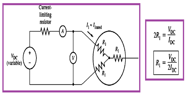
No reactance, no rotor e.m.f. and no core loss can appear in a DC measurement, which is exactly why it is done first.
The no-load test. Average the three line currents and reduce the voltage to a phase value:
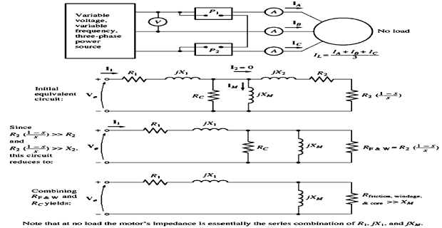
Strip the stator copper loss out of the no-load input to leave the rotational and core losses:
This 371 W is core loss plus friction and windage together; Problem 5 shows how a run at several voltages splits it.
The locked-rotor test, taken at 15 Hz so that the rotor resistance is measured at a realistic slip frequency:
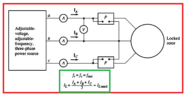
Resolve the locked-rotor impedance and correct the reactance to 60 Hz:
The completed per-phase circuit:
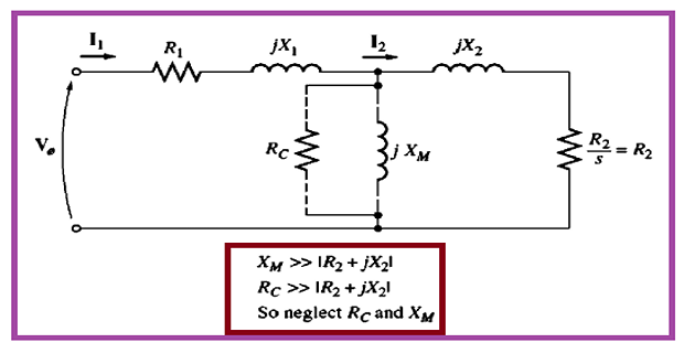
| Parameter | Value | Source |
|---|---|---|
| \(R_1\) | 0.243 Ω | DC test |
| \(R_2'\) | 0.151 Ω | Locked rotor minus DC |
| \(X_1 = X_2'\) | 0.67 Ω | Locked rotor, corrected to 60 Hz, halved |
| \(X_m\) | 14.03 Ω | No load minus \(X_1\) |
| Core loss + windage | 371.3 W | No load minus stator copper |
Reduce the stator side to a Thevenin equivalent, as Set 28, Problem 6 requires before any pull-out calculation:
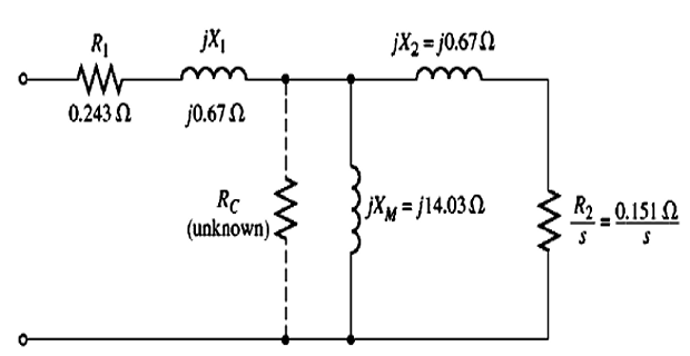
From \(V_{Th} = V_\phi X_m/\sqrt{R_1^2+(X_1+X_m)^2} = 120\times14.03/14.70\) and \(R_{Th} \approx R_1\left(X_m/(X_1+X_m)\right)^2 = 0.243\times(14.03/14.70)^2\).
The slip at pull-out torque:
The pull-out torque. A 4-pole 60 Hz machine has \(N_s = 1800\) rpm, so \(\omega_s = 188.5\) rad/s:
Against a rated torque of roughly \(7.5\ \text{hp} = 5.6\ \text{kW}\) at about 1750 rpm, or 30 N·m, this is a pull-out margin of about 2.2 — entirely normal for a general-purpose cage machine.
Tests on a 460 V, 60 Hz, 4-pole, 3-phase star-connected, 25 hp induction motor give, per phase and at rated frequency, a blocked-rotor resistance \(R_{BL} = 0.50\ \Omega\), a blocked-rotor reactance \(X_{BL} = 1.90\ \Omega\), a no-load impedance \(|Z_{nl}| = 12.6\ \Omega\) and a DC stator resistance \(R_1 = 0.20\ \Omega\). The tests cannot separate \(X_1\) from \(X_2'\). Using the NEMA design-class rule,
- find \(X_1\), \(X_2'\) and \(X_m\) if the machine is Design B
- repeat for Design A and Design C
- compute the slip at maximum torque and the pull-out torque for each, and say how much the choice of split actually matters.
Understand what the tests can and cannot see. The blocked-rotor test measures the two leakage reactances in series, and no terminal measurement can distinguish them — there is no accessible node between them. What is measured is only
The rotor resistance is unambiguous, though: \(R_2' = R_{BL}-R_1 = 0.50-0.20 = 0.30\ \Omega\).
The NEMA convention assigns the split by design class, reflecting the rotor-slot geometry each class uses:
| Design class | \(X_1\) | \(X_2'\) | Rotor construction |
|---|---|---|---|
| A and wound rotor | \(0.5X_{BL}\) | \(0.5X_{BL}\) | Normal slots, low resistance |
| B | \(0.4X_{BL}\) | \(0.6X_{BL}\) | Deep, narrow bars — high rotor leakage |
| C | \(0.3X_{BL}\) | \(0.7X_{BL}\) | Double cage |
| D | \(0.5X_{BL}\) | \(0.5X_{BL}\) | High-resistance bars |
Design B, the default for a general-purpose 25 hp machine:
Designs A and C by the same rule:
Note that \(X_m\) moves in the opposite direction to \(X_1\), because their sum is pinned by the no-load measurement.
Now the Thevenin quantities for each case, with \(V_\phi = 460/\sqrt3 = 265.6\ \text{V}\) and \(\omega_s = 188.5\ \text{rad/s}\):
| Class | \(X_1\) | \(X_2'\) | \(X_m\) | \(V_{Th}\) | \(R_{Th}\) | \(X_{Th}\) |
|---|---|---|---|---|---|---|
| A / D | 0.95 | 0.95 | 11.65 | 245.5 V | 0.171 Ω | 0.881 Ω |
| B | 0.76 | 1.14 | 11.84 | 249.5 V | 0.177 Ω | 0.717 Ω |
| C | 0.57 | 1.33 | 12.03 | 253.5 V | 0.182 Ω | 0.547 Ω |
The key observation. Add \(X_{Th}\) and \(X_2'\) in each row:
All three are close to \(X_{BL} = 1.90\ \Omega\), and for the reason that \(X_{Th}\approx X_1\) while \(X_1+X_2' = X_{BL}\) is fixed. The quantity that governs both pull-out results is therefore almost independent of how the split is made.
Slip at maximum torque and pull-out torque, with \(R_2' = 0.30\ \Omega\) throughout:
| Class | \(\sqrt{R_{Th}^2+(X_{Th}+X_2')^2}\) | \(s_{maxT}\) | \(T_{max}\) |
|---|---|---|---|
| A / D | 1.839 Ω | 0.163 | 238.7 N·m |
| B | 1.865 Ω | 0.161 | 242.7 N·m |
| C | 1.886 Ω | 0.159 | 247.3 N·m |
The pull-out slip varies by 2.5% across the whole range of design classes and the pull-out torque by 3.6% — a spread far smaller than the uncertainty in the test readings themselves.
Where the split does matter. It is not the torque but the magnetising branch and the stator voltage drop:
These affect the no-load current, the power factor at light load and the core-loss estimate. For torque and slip predictions the convention can be applied with a clear conscience; for magnetising-current studies it should not be leaned on.
A 400 V, 50 Hz, 4-pole, 3-phase star-connected induction motor with a stator resistance of 0.35 Ω per phase is run uncoupled at rated frequency while the supply voltage is reduced in steps. The line readings are
| Line voltage | 400 V | 350 V | 300 V | 250 V | 200 V |
|---|---|---|---|---|---|
| No-load current | 8.50 A | 7.35 A | 6.25 A | 5.20 A | 4.20 A |
| No-load input | 1256 W | 1054 W | 880 W | 733 W | 613 W |
Separate the friction and windage loss from the core loss, and state the core loss at rated voltage.
Identify what the no-load input contains. With the shaft uncoupled the mechanical output is zero, so every watt drawn becomes a loss:
The rotor copper loss is genuinely negligible here: the no-load slip is a few tenths of a per cent, so \(P_{cu2} = sP_g\) amounts to a watt or two.
Remove the stator copper loss from each reading, since it is the one term that depends on the current rather than on the voltage:
| \(V_L\) | \(I_0\) | \(P_0\) | \(3I_0^2R_1\) | \(P' = P_i+P_{fw}\) | \(V_L^2\) |
|---|---|---|---|---|---|
| 400 V | 8.50 A | 1256 W | 75.9 W | 1180.1 W | 160 000 |
| 350 V | 7.35 A | 1054 W | 56.7 W | 997.3 W | 122 500 |
| 300 V | 6.25 A | 880 W | 41.0 W | 839.0 W | 90 000 |
| 250 V | 5.20 A | 733 W | 28.4 W | 704.6 W | 62 500 |
| 200 V | 4.20 A | 613 W | 18.5 W | 594.5 W | 40 000 |
Use the different voltage dependence of the two remaining losses. Core loss follows the flux, and hence the voltage, roughly as a square; friction and windage depends on speed, which barely changes:
So plotting \(P'\) against \(V_L^2\) should give a straight line whose intercept is the friction and windage loss — the loss that survives when the flux is taken to zero.
Take the two extreme points to fix the line:
Check the fit at the intermediate points — a curved plot would mean the square law has been broken by saturation:
| \(V_L\) | Measured \(P'\) | Fitted \(399+kV_L^2\) | Difference |
|---|---|---|---|
| 350 V | 997.3 W | 996.8 W | +0.5 W |
| 300 V | 839.0 W | 838.2 W | +0.8 W |
| 250 V | 704.6 W | 704.0 W | +0.6 W |
Agreement to better than a watt, so the straight line is genuine and the extrapolation is trustworthy. A least-squares fit through all five points gives 399.5 W, confirming the two-point estimate.
The core loss at rated voltage is what is left after removing the intercept:
Why the separation is worth the extra readings. The two losses behave differently in every subsequent calculation:
| Loss | Value | Where it leaves the power flow | Depends on |
|---|---|---|---|
| Core loss | 780 W | At the stator, before the air gap | \(V^2\) and frequency |
| Friction and windage | 400 W | At the shaft, after \(P_m\) | Speed only |
Lumping them together, as Problem 1 was content to do, puts 400 W in the wrong place in the ledger. It leaves the total loss right but the air-gap power — and therefore the torque — wrong.
The machine of Problem 5 — 400 V, 50 Hz, 4-pole, star-connected, \(R_1 = 0.35\ \Omega\) per phase, no-load 400 V, 8.50 A, 1256 W, of which 400 W is friction and windage — also gave a blocked-rotor test at rated frequency of 99 V, 40 A, 2880 W. Using the approximate equivalent circuit, predict at a full-load slip of 4%
- the referred rotor current and the line current
- the power factor
- the shaft output power
- the shaft torque
- the efficiency.
Extract the series-branch parameters from the blocked-rotor test:
Build the exciting branch from the core loss alone, not from the whole no-load input. Problem 5 established the split:
If the whole 1256 W were put into \(R_0\), the friction and windage would be charged to the machine twice — once at the terminals and again when it is deducted from \(P_m\). Here the shunt branch carries the core loss only.
Solve the series branch at 4% slip:
Add the exciting current to get the line current and the power factor:
Air-gap power, mechanical power and shaft output:
Input power, shaft torque and efficiency:
Verify by the loss ledger, which must close exactly if the exciting branch was built correctly:
| Term | Expression | Value |
|---|---|---|
| Shaft output | — | 20 819 W |
| Stator copper loss | \(3I_2'^2R_1\) | 1238 W |
| Core loss | from Problem 5 | 780 W |
| Rotor copper loss | \(sP_g\) | 884 W |
| Friction and windage | from Problem 5 | 400 W |
| Total | — | 24 121 W ✓ |
The ledger closing to the watt is the strongest available check that the parameters, the slip and the loss split are all consistent.
A sanity check on the prediction itself. The predicted full-load current of 37.9 A is close to the 40 A used in the blocked-rotor test, which is how such a test should be set up; the starting current would be \(230.9/1.429 = 162\ \text{A}\), or 4.3 times full load, and the output of 20.8 kW at 400 V is consistent with a 28 hp frame. Nothing in the answer is physically out of range.
Key Formulas
| Quantity | Relation | Notes |
|---|---|---|
| DC test, star | \(R_1 = V_{DC}/2I_{DC}\) | Two phases in series — Problem 3 |
| No-load power factor | \(\cos\phi_0 = P_0/\sqrt3V_LI_0\) | Typically 0.1–0.2 — Problem 1 |
| Exciting components | \(I_w = I_0\cos\phi_0,\ I_\mu = I_0\sin\phi_0\) | Problem 1 |
| Shunt branch | \(R_0 = V_{ph}/I_w,\quad X_0 = V_{ph}/I_\mu\) | Per phase — Problem 1 |
| No-load impedance | \(|Z_{nl}| = V_{ph}/I_0 \approx X_1+X_m\) | Gives \(X_m\) once \(X_1\) is known — Problems 3, 4 |
| Blocked-rotor resistance | \(R_{01} = P_{BR}/3I^2 = R_1+R_2'\) | Independent of test frequency — Problem 2 |
| Blocked-rotor reactance | \(X_{01} = \sqrt{|Z_{01}|^2-R_{01}^2}\) | At the test frequency — Problem 2 |
| Frequency correction | \(X_{01}\big|_{f_r} = (f_r/f_t)X_{01}\big|_{f_t}\) | Reactance only — Problems 2, 3 |
| Leakage split | \(X_1 = X_2' = 0.5X_{01}\) (A, D); \(0.4/0.6\) (B); \(0.3/0.7\) (C) | NEMA convention — Problem 4 |
| No-load loss split | \(P_0 = 3I_0^2R_1+P_i+P_{fw}\) | Problems 3, 5 |
| Windage by extrapolation | \(P_i+P_{fw} = P_{fw}+kV_L^2\) | Intercept at \(V=0\) is \(P_{fw}\) — Problem 5 |
| Starting current | \(I_{st} = V_{ph}/|Z_{01}| = I_{BR}\dfrac{V_{rated}}{V_{BR}}\) | Problems 1, 2 |
| Starting torque | \(T_{st} = 3I_{st}^2R_2'/\omega_s\) | Air-gap power at \(s=1\) — Problem 2 |
| Thevenin values | \(V_{Th} = V_{ph}\dfrac{X_m}{\sqrt{R_1^2+(X_1+X_m)^2}},\ R_{Th}\approx R_1\left(\dfrac{X_m}{X_1+X_m}\right)^2\) | Problems 3, 4 |
| Pull-out slip and torque | \(s_{maxT} = \dfrac{R_2'}{\sqrt{R_{Th}^2+(X_{Th}+X_2')^2}},\ T_{max} = \dfrac{3V_{Th}^2}{2\omega_s[R_{Th}+\sqrt{\cdots}]}\) | Problems 3, 4 |
Common Mistakes
Taking the DC reading as the per-phase resistance. A star winding presents two phases in series, so \(R_1 = V_{DC}/2I_{DC} = 0.243\ \Omega\) in Problem 3, not 0.486 Ω. Every later parameter inherits the error.
Correcting the blocked-rotor resistance for frequency. Only the reactance scales. In Problem 2 the wattmeter gives \(R_{01} = 0.748\ \Omega\) at 12.5 Hz and that number is used unchanged at 50 Hz.
Forgetting to correct the reactance at all. Problem 2's uncorrected value predicts 283 A of starting current instead of 137 A — an error of more than 100%.
Treating the whole no-load input as core loss. It also contains the no-load stator copper loss and the friction and windage — 76 W and 400 W of the 1256 W in Problem 5, so the core loss is 780 W, not 1256 W.
Charging the friction and windage twice. If \(R_0\) is built from the whole no-load input and \(P_{fw}\) is then also subtracted from \(P_m\), the same 400 W is counted at both ends — the trap Problem 6 avoids by putting only the core loss in the shunt branch.
Assuming the blocked-rotor test can separate \(X_1\) and \(X_2'\). It measures their sum, and only their sum. The design-class rule of Problem 4 is a convention, not a measurement.
Using \(|Z_{nl}|\) as \(X_m\) directly. It is \(X_1+X_m\). In Problem 3 that is a 4.8% error, small but easily avoided once \(X_1\) is known.
Using line voltage where phase voltage belongs. Every impedance in these tests is per phase, so the 25 V of Problem 3 becomes 14.4 V before it is divided by the current.
Using \(R_1\) in place of \(R_{Th}\) in the pull-out formulae. In Problem 3 they are 0.243 Ω and 0.221 Ω, which happens to leave \(s_{maxT}\) unchanged at 11.1%; on a machine with a smaller \(X_m\) the difference would show.
Running the blocked-rotor test at rated voltage. The standstill impedance is a few ohms, so rated voltage would drive four to six times rated current through the windings. The test voltage is chosen to give rated current — 83 V in Problem 1, 99 V in Problem 6.
The circuit of Set 28 now has numbers in it, obtained without loading the machine, without opening it, and without any information the nameplate does not carry. Three measurements — a DC reading, a run at no load and a run with the rotor clamped — fix five parameters, and Problem 6 turned those five into a complete prediction of full-load current, torque and efficiency.
The same two test results support a second, older method that dispenses with the circuit algebra altogether. Plot the no-load current phasor and the blocked-rotor current phasor on the complex plane and the locus of the stator current at every slip between them turns out to be a circle. Once it is drawn, output, torque, slip, power factor and efficiency at any load are read off as lengths on the diagram.
Next: Set 30 — The Circle Diagram, where the no-load and blocked-rotor points construct the locus, the output and torque lines are located, and full-load performance is obtained by measurement rather than calculation.