Problem-1
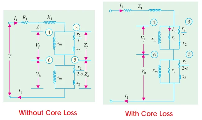
Discuss the revolving field theory of single-phase induction motors. Find the mechanical power output at a slip of 0.05 of the 185-W, 4-pole, 110-V, 60-Hz single-phase induction motor, whose constants are given below:
| Resistance of the stator main winding | \(R_1 = 1.86~\Omega\) |
| Reactance of the stator main winding | \(X_1 = 2.56~\Omega\) |
| Magnetizing reactance of the stator main winding | \(X_m = 53.5~\Omega\) |
| Rotor resistance at standstill | \(R_2 = 3.56~\Omega\) |
| Rotor reactance at standstill | \(X_2 = 2.56~\Omega\) |
Total circuit impedance:
Solution
Problem-2
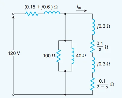
A 120 V, 60 Hz, four-pole, single-phase induction motor has the approximate equivalent circuit shown in Fig. When the rotor rotates at 1764 rpm, estimate the torque it develops. Disregard the effects of the magnetizing impedance.
The torque is
\[\begin{aligned} T&=\frac{I_m^2}{\omega_s}\left(\frac{0.5R_2}{s}-\frac{0.5R_2}{s-2}\right)\text{N}\cdot\text{m}\\ & =\frac{22.48^2}{1800 \frac{2 \pi}{60}}\left(\frac{0.1}{0.02}-\frac{0.1}{2-0.02}\right) \\ & =13.41-0.135\\ &=13.27 \mathrm{~Nm} \end{aligned}\]
Solution
At \(1764 \mathrm{r} / \mathrm{min}\), the slip is
\[s=\frac{1800-1764}{1800}=0.02 \mathrm{pu}\]The impedance of the circuit is
\[\begin{aligned} Z & =0.15+\frac{0.1}{s}+\frac{0.1}{2-s}+j 1.2 ~\Omega \\ Z & =0.15+\frac{0.1}{0.02}+\frac{0.1}{2-0.02}+j 1.2 \\ & =5.34 \angle 13^{\circ} ~\Omega \end{aligned}\]The current is
\[\begin{aligned} I & =\frac{V}{Z}=\frac{120 \angle 0^{\circ}}{5.34 \angle 13^{\circ}} =22.48 \angle-13^{\circ} \mathrm{A} \end{aligned}\]
Problem-3
A 220-V, 6-pole, 50-Hz, single-winding single-phase induction motor has the following equivalent circuit parameters as referred to the stator.
Neglect the magnetizing current. When the motor runs at 97% of the synchronous speed, compute the following:
The ratio \(E_{mf}/E_{mb}\)
The ratio \(V_f/V_b\)
The ratio \(T_f/T_b\)
The gross total torque.
The ratios \(T_f/\text{(Total torque)}\) and \(T_b/\text{(Total torque)}\)
Redrawing the circuit in symmetrical form and taking \(X=\infty\) :
 \[\begin{aligned} &\begin{aligned} \text { Impedance to } V_f & =\frac{1}{2}\left[\left(3+\frac{1.5}{0.03}\right)+j(5+2)\right] =\frac{1}{2}(53+j 7) \\ \text { Impedance to } V_b& =\frac{1}{2}\left[\left(3+\frac{1.5}{1.97}\right)+j(5+2)\right] =\frac{1}{2}(3.76+j 7) \\ \frac{V_f}{V_b} & =\frac{|53+j 7|}{|3.76+j 7|}=6.73 \end{aligned} \end{aligned}\]
The ratio \(T_f/T_b\)
\[\begin{aligned} \frac{T_f}{T_b} & =\frac{P_{g f}}{P_{g b}}=\frac{\frac{1}{2} I_m^2 R_2 / s}{\frac{1}{2} I_m^2 R_2 /(2-s)} \\ & =\frac{2-s}{s}=\frac{2-0.03}{0.03}=65.7 \end{aligned}\]
- Total impedance as seen from stator terminal :\[\begin{aligned} Z & =\frac{1}{2}[(53+j 7)+(3.76+j 7)] =28.38+j 7=29.2 \angle 13.9^{\circ} \\ I_m & =\frac{220}{29.2}=753 \mathrm{~A} \\ n_s & =\frac{120 \times 50}{6}=1000 \mathrm{rpm} \\ \omega_s & =\frac{2 \pi \times 1000}{60}=104.72 \mathrm{rad} / \mathrm{s} \\ T_f & =\frac{1}{\omega_s} I_m^2 \frac{R_2}{2 s} \qquad T_b =\frac{1}{\omega_s} I_m^2 \frac{R_2}{2(2-s)} \\ T_{\text {total }} & =T_f-T_b \\ T_{\text {total }} & =\frac{I_m^2 R_2}{2 ~\Omega_s}\left(\frac{1}{s}-\frac{1}{2-s}\right) \\ & =\frac{(7.53)^2 \times 1.5}{2 \times 104.72}\left(\frac{1}{0.03}-\frac{1}{1.97}\right) =13.31 \mathrm{Nm} \end{aligned}\]
The ratios \(T_f/\text{(Total torque)}\) and \(T_b/\text{(Total torque)}\)
\[\begin{aligned} & \frac{T_f}{T_{\text {total }}}=\frac{1 / s}{1/s-1 /(2-s)}=\frac{1}{1-\frac{s}{2-s}}=1.015 \\ & \frac{T_b}{T_{\text {total }}}=\frac{1 /(2-s)}{1 / s-1 /(2-s)}=\frac{1}{\frac{2-s}{s}-1}=0.015 \end{aligned}\]
Solution
Slip \(s=1-0.97 = 0.03\)
From the equivalent circuit:
 \[\begin{aligned} \frac{E_{m f}}{E_{m b}} & =\frac{Z_f}{Z_b}=\frac{\left|j X \|\left(\frac{R_2}{s}+j X_2\right)\right|}{\left|j X \|\left(\frac{R_2}{2-s}+j X_2\right)\right|} =\frac{\left|R_2 / s+j X_2\right|}{\left|R_2(2-s)+j X_2\right|}\\ &\text{Magnetising current neglected}~\Rightarrow X=\infty\\ & =\frac{|1.5 / 0.03+j 2|}{|1.5 /(2-0.03)+j 2|}=23.38 \end{aligned}\]