Problem-1
A 6-pole, 50-Hz, 1-phase induction motor runs at a speed of 900 rpm. Determine the frequency of currents in the cage rotor?
Solution
The two rotor current frequencies are :
Problem-2
For a single-phase motor of 2 HP rating, supply voltage is 240 V ac. If the efficiency is 70% and power factor is 0.8, find the input current.
Solution
Problem-3
A 4-pole single-phase induction motor is rotating in a clockwise direction at a speed of 1000 rpm having a voltage of 100 V with a frequency of 50 Hz. At a standstill, if the rotor resistance is 1.7 \(\Omega\), then in the backward branch what will be the effective resistance?
Solution
The effective rotor resistance in the forward branch \(\left(R_f\right)\)
\[R_f=\frac{R_2^{\prime}}{2 s}\]The effective rotor resistance in the backward branch \(\left(R_b\right)\)
\[R_b=\frac{R_2^{\prime}}{2(2-s)}\]Where \(R_2{ }^{\prime}=\) Standstill rotor resistance referred to as the main stator winding.
Problem-4
A 6 pole, 50 Hz induction motor has an equivalent rotor resistance of 0.01 \(\Omega\)/phase. If its stalling speed is 900 rpm, determine the resistance that must be inserted in rotor windings per phase to obtain maximum torque at starting?
To obtain maximum torque at starting
Rotor resistance \(=\mathrm{R}^{\prime}_2\) at starting \(\mathrm{s}=1\)
\[\begin{aligned} \mathrm{S}_m&=\mathrm{R}^{\prime} 2 / \mathrm{X}_2 \\ \Rightarrow 1 & =R_2^{\prime} / 0.1\\ \Rightarrow R^{\prime}{ }_2 & =0.1 ~\Omega / \text{phase} \\ R_{ext} &=0.1-0.01\\ &=0.09 ~\Omega / \text{phase} \end{aligned}\]
Solution
Problem-5
A single phase, \(230 \mathrm{~V}, 50 \mathrm{~Hz}\), 4 pole, capacitor start induction motor has the following standstill impedance.
Determine the value of the starting capacitor required to produce \(90^{\circ}\) phase difference between the current in the main and auxiliary windings.
- Total impedance of auxiliary winding :\[\begin{aligned}&\overrightarrow{Z_{\mathrm{aw}}}=\overrightarrow{Z_{\mathrm{a}}}+\frac{1}{\mathrm{j\omega C}}\\&=9-\mathrm{j} (\frac{1}{\omega C}-6)=Z_{\mathrm{aw}}\angle-\theta_{a} \\ \theta_{a} & =\tan^{-1}\frac{(\frac{1}{\omega C}-6)}{9} \end{aligned}\]
Phase difference :
\[\begin{aligned} &\theta_{m} +\theta_{a} =90^{\circ}\\ &\tan^{-1}\left(\frac{\frac1{\omega C}-6}{9}\right)+32^{\circ}=90^{\circ} \Rightarrow& \frac{1}{\omega C}=20.4 \end{aligned}\]\[C=\frac{1}{2\pi\times50\times20.4}=156.03~ \mu F\]
Solution
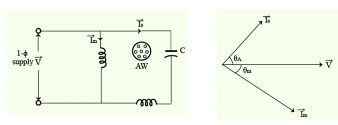
\(\overrightarrow{I_m}\) lags behind voltage \(\vec{V}\) by angle \(\theta_m = 32^{\circ}\)
Problem-6
A 120 V, 60 Hz, single-phase induction motor of the capacitor-start type has a main winding with 180 effective turns and an auxiliary starting winding with 250 effective turns. With the rotor stationary, the input impedance of the main winding is \(5+j10~\Omega\) and that of the auxiliary winding is \(13.89 + j15.50~\Omega\).
Determine at standstill:
The magnitude of the forward and backward-rotating fields
The size of the starting capacitor necessary to yield a single rotating magnetic field at starting.
- The positive-sequence component of the auxiliary winding’s mmf\[{F}_{a_1}=j{F}_{m_1}=1349.10\angle{-4.5^\circ}\text{A rms}\]
- the negative-sequence component\[{F}_{a_2}=-j{F}_{m_2}=1041.7\angle{-111.6^\circ}\text{A rms}\]
Thus, the net forward-rotating field is
\[\begin{aligned} {F}_1={F}_{a_1}+j {F}_{m_1} & =1349.1\left(1 \angle-4.5^{\circ}+1 \angle-4.5^{\circ}\right) \\ & =2,698.2 \angle-4.5^{\circ} \mathrm{A} \mathrm{rms} \end{aligned}\]The net backward-rotating field is
\[\begin{aligned} {F}_2={F}_{a_2}+j {F}_{m_2} & =1041.7\left(1 \angle-111.6^{\circ}+1 \angle-21.6^{\circ}\right) \\ & =90.9~ \angle 155.9^{\circ} \mathrm{A} \mathrm{rms} \end{aligned}\]
To have a single rotating field, the backward-rotating mmf must be equal to zero. That is,
\[\frac{1}{2}(120)\left(\frac{180}{5+j 10}+j \frac{250}{Z_a}\right)=0\]The impedance of the auxiliary winding is
\[Z_a=13.89+j\left(15.5-X_c\right)\]where \(X_c\) is the reactance of the capacitor.
From the last two relationships,
\[\begin{aligned} Z_a & =-j\left(\frac{250(5+j 10)}{180}\right)=13.89+j\left(15.5-X_c\right) \\ X_c &=22.44 ~\Omega\\ \Rightarrow~C & =\frac{1}{\omega X_c} =\frac{1}{2 \pi(60)(22.44)} =118.2 \mu \mathrm{F} \end{aligned}\]
Solution
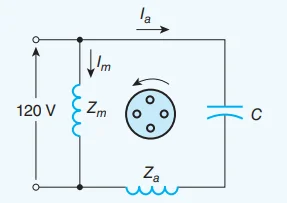
The positive (\({F}_{m_1}\)) and negative (\({F}_{m_2}\)) sequence components of the motor’s mmf: