Set 2 — Magnetic Circuits with Air Gaps
A magnetic circuit only becomes interesting once it is interrupted. This set works seven structures containing air gaps — two gaps in series across a machine's rotor, two in parallel, one in a laboratory inductor, two in the outer limbs of a three-legged core, and one in the shared limb of a two-winding core — and in every one of them the gap decides the answer.
The reason is a missing symbol. The gap reluctance \(g/\mu_0 A_g\) carries no \(\mu_r\), so a gap thousands of times shorter than the iron path is still hundreds of times more reluctant. That single asymmetry justifies the \(\mu_r = \infty\) assumption used in Problems 1, 2 and 5, and Problem 6 measures exactly what it costs when the assumption is dropped.
The gap reluctance has no \(\mu_r\) in it, which is why it dominates:
\[ \mathcal{R}_g = \frac{g}{\mu_0 A_g}, \qquad \mathcal{R}_c = \frac{l_c}{\mu_0\mu_r A_c} \]Series and parallel work as in a resistive network. Paths carrying the same flux add their reluctances; paths sharing the same mmf combine as \(\mathcal{R}_1\mathcal{R}_2/(\mathcal{R}_1+\mathcal{R}_2)\), and the flux divides in inverse proportion — the opposite branch on top:
\[ \Phi_1 = \Phi\,\frac{\mathcal{R}_2}{\mathcal{R}_1+\mathcal{R}_2} \]With \(\mu_r = \infty\) the whole mmf appears across the gaps. The iron is then a perfect conductor of flux and only the gap lengths matter — Problems 1, 2 and 5.
Neglecting fringing means the gap area equals the core area, so \(B_g = B_c\) and the flux is continuous across the gap. Every problem here states that assumption; in reality fringing enlarges \(A_g\) and lowers \(\mathcal{R}_g\) slightly.
Inductance and stored energy come straight from the total reluctance:
\[ L = \frac{\lambda}{i} = \frac{N\Phi}{i} = \frac{N^2}{\mathcal{R}}, \qquad W = \tfrac12 L i^2 \]A changing flux induces a voltage by Faraday's law, and because the area is fixed it is the density that is differentiated:
\[ e = \frac{d\lambda}{dt} = N\frac{d\Phi}{dt} = N A_c \frac{dB_c}{dt} \]When the core is nonlinear, stop using reluctances. Read \(H_c\) off the magnetisation curve at the required \(B_c\) and add mmf drops around the loop instead — Problem 4:
\[ NI = \sum H_k l_k = H_c l_c + H_g g \]
The magnetic structure of a synchronous machine is shown in the figure. The stator and rotor iron may be taken as infinitely permeable, \(\mu_r = \infty\), so that the flux crosses only the two air gaps between them. The field winding has \(N = 1000\) turns and carries \(I = 10\) A; each gap is \(g = 1\) cm long and the gap cross-section is \(A_g = 2000\ \text{cm}^2\). Find:
- the air-gap flux \(\Phi\);
- the air-gap flux density \(B_g\).
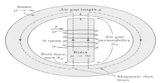
Count the gaps before doing anything else. The flux path leaves the rotor, crosses into the stator, travels round the stator yoke and re-enters the rotor — so it crosses two gaps in series, of total length \(2g\). By symmetry the flux density in each is the same.
Only the gaps are reluctant. With \(\mu_r = \infty\) the iron contributes nothing, so the entire magnetic circuit is two gaps in series:
Remember the conversions: \(2000\ \text{cm}^2 = 0.2\ \text{m}^2\) and \(2g = 0.02\ \text{m}\).
The flux is then the mmf divided by that reluctance:
The gap flux density is best taken from the unrounded flux, or better still written directly so that the area cancels:
Rounding \(\Phi\) to 0.13 Wb before dividing would give 0.65 T, an error of 3.5% introduced purely by the arithmetic. Carry full precision to the last step.
Sanity check on the number. Machine gap densities sit between about 0.5 and 1.0 T — high enough to give useful torque, low enough to keep the stator teeth out of saturation. 0.628 T is squarely in that range, and the 10 A field current producing it is likewise realistic for a winding of 1000 turns.
The magnetic circuit of the figure consists of an \(N\)-turn winding on a magnetic core of infinite permeability with two parallel air gaps, of lengths \(g_1\) and \(g_2\) and areas \(A_1\) and \(A_2\) respectively. Neglect fringing at the gaps. Find:
- the inductance of the winding;
- the flux density \(B_1\) in gap 1 when the winding carries a current \(i\).
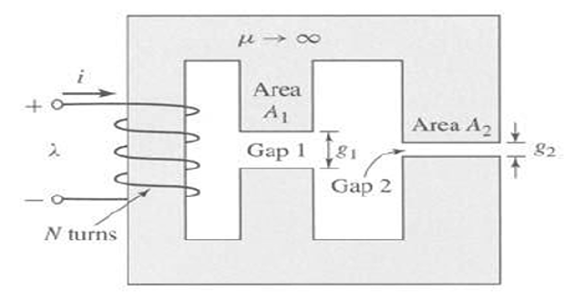
Draw the equivalent circuit. The winding is a source of mmf \(\mathcal{F} = Ni\); the iron is a perfect conductor of flux; the two gaps therefore hang directly across the source, in parallel:
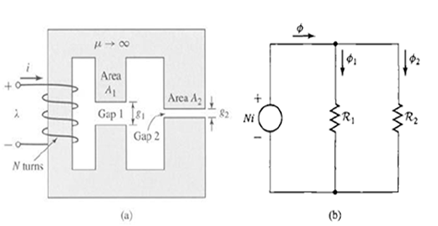
The total reluctance is the parallel combination of the two gap reluctances, and the total flux follows:
The inductance is the flux linkage per ampere. Substituting the two reluctances gives a result in the physical dimensions alone:
The two terms are simply the inductances the gaps would have separately: parallel reluctances mean inductances in addition, \(L = L_1 + L_2\). Adding a second gap path therefore increases the inductance, whereas putting a gap in series with the first would reduce it.
The density in gap 1 alone. Because the branches are in parallel, gap 1 sees the full mmf \(Ni\) regardless of what the other branch is doing:
Note what has cancelled: \(B_1\) depends on \(g_1\) only — not on \(A_1\), and not on \(g_2\) or \(A_2\) at all. Halving \(g_1\) doubles \(B_1\); widening gap 2 changes it not at all.
Check the flux sums. Adding the branch fluxes must return the total:
and dividing by \(i\) after multiplying by \(N\) returns the inductance found above — the two parts of the problem are consistent.
The gapped core of the figure has \(A_c = A_g = 9\ \text{cm}^2\), \(l_c = 30\) cm, \(g = 0.050\) cm, \(N = 500\) turns and \(\mu_r = 70{,}000\) — the circuit of Set 1, Problem 5, for which \(\mathcal{R}_c = 3.79\times10^{3}\) and \(\mathcal{R}_g = 4.42\times10^{5}\ \text{AT/Wb}\), and a coil current of 0.80 A produces \(B_c = 1.0\) T. Find:
- the inductance \(L\);
- the magnetic stored energy \(W\) at \(B_c = 1.0\) T;
- the induced voltage \(e\) for a 60 Hz time-varying core flux density \(B_c = 1.0\sin\omega t\) T, with \(\omega = 2\pi(60) = 377\ \text{rad/s}\).
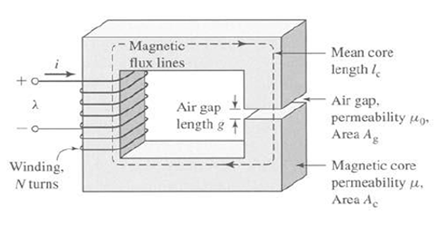
Inductance from the total reluctance. The two reluctances are in series, and the flux linkage per ampere is:
The gap reluctance is 117 times the core's, so to a good approximation \(L \approx N^2/\mathcal{R}_g\). Close the gap and the same winding would measure about 66 H — and would be hopelessly nonlinear.
Stored energy at the stated operating point, using the current found in Set 1, Problem 5:
Since the reluctance — and hence the mmf — is 99% gap, so is the energy. An air gap is where a magnetic circuit stores what it holds, which is why every inductor meant to store energy has one.
The induced voltage, from Faraday's law. The area is constant, so only the density is differentiated:
Check against the transformer emf equation, which Part 3 uses throughout. The rms value of that voltage is:
The two agree because \(4.44 = 2\pi/\sqrt2\) — the same calculation with the differentiation already performed.
The same core is used again — \(A_c = A_g = 9\ \text{cm}^2\), \(g = 0.050\) cm, \(l_c = 30\) cm, \(N = 500\) turns — but the core material is no longer described by a constant permeability. Instead it is specified by the dc magnetisation curve of the figure. Neglecting fringing, find the current \(i\) required to produce \(B_c = 1\) T.
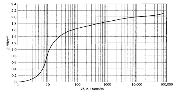
Change of method, and why. A reluctance \(l/\mu_0\mu_r A\) presupposes a single \(\mu_r\); a magnetisation curve says there is none. So work in mmf drops instead, using Ampère's law around the loop:
Read the core field strength off the curve at the required density. At \(B_c = 1.0\) T the figure gives:
The gap needs no curve. Air is linear, and with no fringing the gap carries the same density as the core, \(B_g = B_c = 1.0\) T:
Add the drops and divide by the turns:
The gap takes 99.2% of the ampere-turns. Setting \(\mathcal{F}_c = 0\) outright would have given 0.796 A — the same answer to two figures.
Reconcile with Problem 3. The curve reading implies an effective relative permeability at this point of
which is the 70,000 assumed in Problem 3, and the current is the same 0.80 A. The two methods are consistent because 1.0 T lies on the straight part of this material's curve; push to 1.8 T and \(H_c\) would rise by orders of magnitude while the gap drop only doubled.
An inductor is wound on the gapped core of the figure. The core has cross-section \(A_c = 1.8\times10^{-3}\ \text{m}^2\) and mean length \(l_c = 0.6\) m, the air gap is \(g = 2.3\times10^{-3}\) m, and the winding has \(N = 83\) turns. Assume the core is of infinite permeability and neglect fringing at the gap and leakage flux. Find:
- \(\mathcal{R}_c\) and \(\mathcal{R}_g\);
- for a current \(i = 1.5\) A, the total flux \(\Phi\), the flux linkage \(\lambda\) of the coil, and the coil inductance \(L\);
- the number of turns required to achieve an inductance of 12 mH;
- with that winding, the inductor current which results in \(B_c = 1.0\) T.
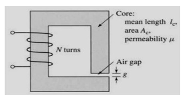
The two reluctances. With \(\mu \to \infty\) the iron vanishes from the problem, and with no fringing the gap area is the core area:
The whole magnetic circuit is now this one number.
Flux, flux linkage and inductance at \(i = 1.5\) A:
Confirmed independently by \(L = N^2/\mathcal{R}_g = 83^2/1.017\times10^{6} = 6.78\ \text{mH}\), which also shows that \(L\) does not depend on the current — the point of gapping the core.
Turns for a specified inductance. Since \(L = N^2/\mathcal{R}_g\) and the reluctance is unaffected by the winding:
Equivalently \(83\sqrt{12/6.78} = 110\): raising the inductance by 77% needs only 33% more turns, because of the square law.
The current that saturates the core to 1.0 T. With no fringing \(B_g = B_c\), so the flux is fixed by the core area, and the current follows from the inductance:
This is the rating of the inductor: beyond about 16.5 A the real core would leave its linear region and \(L\) would collapse. (Rounding 110.5 down to 110 turns actually gives \(L = 11.9\) mH and a saturation current of 16.6 A; the design value 16.5 A quoted at the nominal 12 mH is the conservative figure.)
The three-limb core of the figure carries a 1000-turn coil on the central limb, energised at 0.5 A. Each outer limb is interrupted by an air gap. Find the flux and flux density in each of the outer limbs and in the central limb, assuming \(\mu_r\) for the iron of the core to be (a) \(\infty\) and (b) 4500. Neglect fringing, and neglect the effect of the gaps on the iron path lengths.
| Quantity | Central limb | Outer limb 1 | Outer limb 2 |
|---|---|---|---|
| Cross-section | 50 cm2 | 25 cm2 | 25 cm2 |
| Air gap | none | 2 mm | 1 mm |
| Mean iron length | 45 cm | 120 cm | 120 cm |
| Winding | 1000 turns, 0.5 A | — | — |
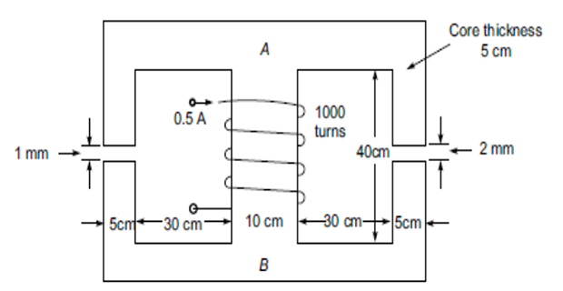
The driving mmf, common to both outer branches:
aWith \(\mu_r = \infty\), only the gaps count. The iron carries no mmf drop, so each outer limb sees the whole 500 AT across its own gap alone:
Each outer limb independently:
Half the gap, twice the flux: the branches are in parallel across a fixed mmf, so the shorter gap takes proportionally more.
The central limb carries the sum, by continuity of flux at the junction:
bWith \(\mu_r = 4500\) the iron must be added as reluctance in series within each branch. The analogous electrical circuit is shown below; the iron path lengths come from the figure's dimensions:
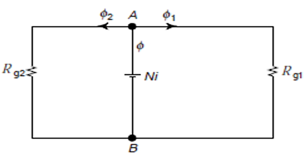
The iron reluctances:
Each is roughly an eighth of the gap it sits with — small, but no longer negligible.
Reduce the network. Each branch is a series pair; the two branches are in parallel; the central limb is in series with the combination:
Total flux and central-limb density:
Divide the flux between the branches, putting the opposite branch reluctance on top:
Check: \(0.653+1.168 = 1.821\ \text{mWb} = \Phi\) ✓
What the iron cost, side by side:
| Quantity | \(\mu_r = \infty\) | \(\mu_r = 4500\) | Change |
|---|---|---|---|
| \(\Phi_1\) (2 mm gap) | 0.785 mWb | 0.653 mWb | −17% |
| \(\Phi_2\) (1 mm gap) | 1.571 mWb | 1.168 mWb | −26% |
| \(\Phi\) (central) | 2.356 mWb | 1.821 mWb | −23% |
| \(B\) (central) | 0.471 T | 0.364 T | −23% |
The short-gap branch suffers most, because its iron reluctance is a larger fraction of its total. Assuming perfect iron overstates the flux by nearly a third here — far more than in Problem 1, where the gap was proportionally much longer.
In the magnetic circuit of the figure the relative permeability of the ferromagnetic material is 1200 and the material has a square cross-section, 2 cm × 2 cm. All dimensions are in centimetres. Two windings, one on each outer limb, each provide 5000 A·t and drive flux in the same direction through the common limb b–e, which contains a 5 mm air gap. Neglect magnetic leakage and fringing. Determine the air-gap flux, the air-gap flux density, and the magnetic field intensity in the air gap.
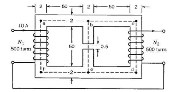
The gap reluctance, with \(A_g = A_c = 2\times2 = 4\ \text{cm}^2 = 4\times10^{-4}\ \text{m}^2\):
The iron of the centre limb, of mean length 51.5 cm excluding the gap, with \(\mu_c = \mu_0\mu_r\):
Half a centimetre of air is twelve times more reluctant than half a metre of this iron. From symmetry the two outer paths are identical, \(\mathcal{R}_{bafe} = \mathcal{R}_{bcde} = 2.58\times10^{6}\ \text{At/Wb}\), corresponding to a mean length of about 156 cm each.
Write the two loop equations. Each loop contains its own outer path plus the shared centre limb, and because the two fluxes reinforce in that limb, the shared reluctance appears in both equations with the same sign:
This is mesh analysis with flux for current, mmf for voltage and reluctance for resistance — the magnetic circuit analogy carried as far as it goes.
Substitute the numbers, in At/Wb and A·t:
Symmetry solves the pair by inspection. The coefficient matrix is symmetric and the two right-hand sides are equal, so \(\Phi_1 = \Phi_2\) and the equations collapse to one:
The gap carries both fluxes:
Check the mmf balance round one loop, which must return the 5000 A·t the winding supplies:
| Section | Flux | Reluctance | mmf drop |
|---|---|---|---|
| Outer path b–a–f–e | 2.07 × 10⁻⁴ Wb | 2.58 × 10⁶ | 533 At |
| Centre limb iron | 4.14 × 10⁻⁴ Wb | 0.85 × 10⁶ | 353 At |
| Air gap | 4.14 × 10⁻⁴ Wb | 9.95 × 10⁶ | 4114 At |
| Total | 5000 At ✓ | ||
The 5 mm gap absorbs 82% of the available ampere-turns even though it is under 1% of the flux path. Note also that \(H_g\) is 1200 times the field intensity in the iron at the same density — the whole story of this set in one ratio.
Key Formulas
| Quantity | Relation | Notes |
|---|---|---|
| Air-gap reluctance | \(\mathcal{R}_g = \dfrac{g}{\mu_0 A_g}\) | No \(\mu_r\) — every problem here |
| Core reluctance | \(\mathcal{R}_c = \dfrac{l_c}{\mu_0\mu_r A_c}\) | Zero when \(\mu_r = \infty\) — Problems 1, 2, 5 |
| Two gaps in series | \(\mathcal{R} = \dfrac{2g}{\mu_0 A_g}\) | Flux crosses the gap twice — Problem 1 |
| Gaps in parallel | \(\mathcal{R}_{eq} = \dfrac{\mathcal{R}_1\mathcal{R}_2}{\mathcal{R}_1+\mathcal{R}_2}\) | Same mmf across each — Problems 2, 6 |
| Flux | \(\Phi = \dfrac{Ni}{\mathcal{R}}\) | Magnetic Ohm's law |
| Flux division | \(\Phi_1 = \Phi\dfrac{\mathcal{R}_2}{\mathcal{R}_1+\mathcal{R}_2}\) | Opposite branch on top — Problem 6 |
| Parallel-gap density | \(B_1 = \dfrac{\mu_0 N i}{g_1}\) | Independent of the other branch — Problem 2 |
| Inductance | \(L = \dfrac{\lambda}{i} = \dfrac{N^2}{\mathcal{R}}\) | Constant once gapped — Problems 3, 5 |
| Parallel-gap inductance | \(L = \mu_0 N^2\!\left(\dfrac{A_1}{g_1}+\dfrac{A_2}{g_2}\right)\) | Inductances add — Problem 2 |
| Turns for a target \(L\) | \(N = \sqrt{L\,\mathcal{R}}\) | Square law — Problem 5 |
| Stored energy | \(W = \tfrac12 L i^2\) | Held almost entirely in the gap — Problem 3 |
| Faraday's law | \(e = N A_c \dfrac{dB_c}{dt}\) | Fixed area — Problem 3 |
| RMS emf | \(E = 4.44 f N \Phi_{max}\) | \(4.44 = 2\pi/\sqrt2\) — Problem 3 |
| Ampere's law | \(Ni = H_c l_c + H_g g\) | Use when \(\mu_r\) varies — Problem 4 |
| Gap mmf drop | \(\mathcal{F}_g = \dfrac{B_g g}{\mu_0}\) | Linear in \(B\) always — Problems 4, 7 |
Common Mistakes
Using one gap length where the flux crosses two. A rotor inside a stator is separated by a gap on the way out and on the way back, so the reluctance is \(2g/\mu_0 A_g\) — Problem 1.
Rounding before the last step. Taking \(\Phi = 0.13\) Wb instead of 0.1257 and dividing by the area gives 0.65 T where the true value is 0.628 T — Problem 1.
Putting \(\mu_r\) into the gap formula. The gap is air: \(\mathcal{R}_g = g/\mu_0 A_g\) and \(H_g = B_g/\mu_0\). This is the single most common error in the whole topic — Problems 4 and 7.
Adding parallel gap reluctances. Branches across a common mmf combine as \(\mathcal{R}_1\mathcal{R}_2/(\mathcal{R}_1+\mathcal{R}_2)\), and their inductances add — Problem 2.
Assuming the wider gap carries the larger flux. Flux goes inversely with reluctance, so the 1 mm limb carries twice the flux of the 2 mm limb — Problem 6.
Using a reluctance with a nonlinear core. Once the material is given as a \(B\)–\(H\) curve there is no single \(\mu_r\); read \(H_c\) at the required \(B_c\) and add mmf drops — Problem 4.
Dropping the iron when it is no longer negligible. Perfect iron is a good assumption at \(\mathcal{R}_c/\mathcal{R}_g \approx 1\%\) and a bad one at 12%, where it overstates the flux by 23% — Problem 6.
Forgetting the \(N^2\) in an inductance. Doubling the turns quadruples \(L\) and halves the saturation current — Problem 5.
Mixing Wb, mWb and µWb. A flux of \(1.571\times10^{-3}\) Wb is 1.571 mWb, not 1571 mWb; the slip survives into the flux density unnoticed — Problem 6.
Omitting the shared limb from one of the loop equations. When two windings drive flux through a common gapped limb, that limb's reluctance appears in both equations and carries \(\Phi_1+\Phi_2\) — Problem 7.
Seven circuits, one conclusion: the gap decides. It sets the flux in Problem 1, the flux density in Problem 2, the inductance and the stored energy in Problems 3 and 5, and it takes 82% of the available ampere-turns in Problem 7. The iron's job is only to guide the flux from one face of the gap to the other, and Problem 6 measured the modest price of guiding it imperfectly.
The networks are also becoming circuits in earnest. Problem 6 needed a series–parallel reduction and a flux divider; Problem 7 needed two loop equations and a symmetry argument. That machinery, applied to iron paths rather than gaps, is what the next set is about.
Next: Set 3 — Series and Parallel Magnetic Circuits, where composite iron paths of differing section and material are combined, the flux divider is used in anger, and circuits that cannot be solved without iteration make their first appearance.