Set 22 — Autotransformers
Join the primary and the secondary of a transformer at one point and the two circuits become one winding with a tapping. The turns ratio still fixes the voltages and the m.m.f. balance still fixes the currents, but part of the load current now reaches the load without passing through the magnetic circuit at all. This set follows that current through the winding and works out what it costs and what it saves.
The four problems build one idea. Splitting the output into a conductively and an inductively transferred part explains why only a fraction of the copper is needed, why the saving equals the voltage ratio, and why a two-winding transformer reconnected as an autotransformer can carry many times its nameplate rating on the same iron with the same losses — provided the isolation between the two circuits can be given up.
One winding, one tapping. An autotransformer has a single winding with a tap; the portion between the tap and the common terminal is the common winding, the rest is the series winding. The voltage and current ratios are the ordinary ones, with \(a = N_1/N_2 = V_1/V_2\):
\[ S = V_1I_1 = V_2I_2, \qquad I_1 = \frac{I_2}{a} \]The common winding carries only the difference of the two line currents, because the load current partly flows straight in from the supply:
\[ I_{\text{common}} = \left|I_2 - I_1\right|, \qquad I_{\text{series}} = I_{\text{HV side}} \]The output divides into two paths. Part is carried by the metal of the common connection and part is transformed magnetically:
\[ P_{\text{cond}} = S\times\frac{V_{LV}}{V_{HV}}, \qquad P_{\text{ind}} = S\left(1 - \frac{V_{LV}}{V_{HV}}\right) \]For a step-down unit with \(a > 1\) these are \(S/a\) and \(S(1-1/a)\). The inductively transferred part always equals the volt-amperes of the series winding, and also those of the common winding.
Only the transformed part needs iron and copper, which is where the saving comes from. Comparing winding weights, which go as turns times current:
\[ \frac{W_{\text{auto}}}{W_{\text{2-winding}}} = 1 - \frac{V_{LV}}{V_{HV}}, \qquad \text{saving} = \frac{V_{LV}}{V_{HV}} \]A two-winding transformer reconnected as an autotransformer keeps its winding currents and therefore its losses, but handles far more throughput:
\[ S_{\text{auto}} = S_{\text{2-winding}}\times\frac{V_{HV}}{V_{HV} - V_{LV}} \]The price is isolation. Primary and secondary share a conductor, so a fault or an open common winding puts the full high voltage on the low-voltage terminals. Autotransformers are used only where the two voltages are close and isolation is not required.
An autotransformer supplies a load of 3 kW at 115 V at unity power factor. The applied primary voltage is 230 V. Calculate the power transferred to the load
- inductively
- conductively.
Take the ratio and the two line currents. At unity power factor the kVA and the kW are the same number:
Follow the current through the winding. The supply pushes 13.04 A into the tapping point, and the load draws 26.09 A out of it; the common winding supplies the shortfall:
Half the load current arrives conductively straight from the supply and half is produced by transformer action in the common winding.
Conductively transferred power is the part of the load voltage carried by the current that flows through from the supply:
Inductively transferred power is what the series winding has to develop, namely the voltage difference times the current through it:
The same 1.5 kW from the common winding, as a check that the two windings agree:
The series and common windings always handle the same volt-amperes, because they are the two windings of the transformer hidden inside the autotransformer.
A 2 : 1 ratio is the poorest case for an autotransformer. The magnetically transferred fraction is \(1 - 1/a\), so:
| Ratio \(a\) | Conductive share | Inductive share |
|---|---|---|
| 1.1 | 91% | 9% |
| 2 | 50% | 50% |
| 10 | 10% | 90% |
The nearer the ratio is to unity, the more of the load is carried free by the common connection — and the smaller the machine can be. At \(a = 10\) the saving has almost vanished, which is why autotransformers are not built for large ratios.
The primary and secondary voltages of an autotransformer are 500 V and 400 V respectively. Show the current distribution in the winding when the secondary current is 100 A, and calculate the economy of copper in this particular case.
The ratio and the input current. Volt-amperes in equal volt-amperes out, so
Trace the winding. The whole winding stands across 500 V with a tapping at 400 V. Above the tap is a 100 V series section carrying the input current; below it is a 400 V common section carrying the difference:
| Section | Voltage across it | Current in it | Volt-amperes |
|---|---|---|---|
| Series (input terminal to tap) | 500 − 400 = 100 V | \(I_1 = 80\ \text{A}\) | 8 kVA |
| Common (tap to neutral) | 400 V | \(I_2 - I_1 = 20\ \text{A}\) | 8 kVA |
| Throughput at the terminals | 500 V in / 400 V out | 80 A in / 100 A out | 40 kVA |
The two winding sections each handle 8 kVA, one fifth of the 40 kVA passing through the machine. The copper is sized for 8 kVA; the customer receives 40.
Weigh the copper. The weight of a winding is proportional to its number of turns times the cross-section of its conductor, and the cross-section is proportional to the current it carries. For an ordinary two-winding transformer of the same duty:
The two terms are equal because \(N_1I_1 = N_2I_2\) — the m.m.f. balance of any transformer.
For the autotransformer, the series section has \(N_1 - N_2\) turns carrying \(I_1\) and the common section \(N_2\) turns carrying \(I_2 - I_1\):
Hence the economy:
The same 0.8 that is the voltage ratio \(V_2/V_1\), and the same 0.8 by which the winding volt-amperes fell from 40 kVA to 8 kVA. All three statements are one statement.
A 5 kVA, 110/110 V single-phase, 50 Hz transformer has a full-load efficiency of 95% and an iron loss of 50 W. The transformer is now connected as an autotransformer to a 220 V supply. If it delivers a 5 kW load at unity power factor to a 110 V circuit, calculate the efficiency of the operation and the current drawn by the high-voltage side.
Recover the copper loss from the two-winding efficiency. At full load and unity power factor the output is 5000 W:
Set up the autotransformer connection. The two 110 V windings are joined in series so that their voltages add, giving 220 V across the pair; the junction and one end form the 110 V output. Each winding still has 110 V across it, so the flux and therefore the iron loss are unchanged at 50 W.

Find the winding currents. The load takes
As a two-winding transformer at its 5 kVA rating each winding carried \(5000/110 = 45.5\) A. In this connection, at this load, each carries half of that.
Copper loss falls to a quarter, since it goes as the square of the winding current:
Efficiency as an autotransformer:
Up from 95% for the same core, the same copper and the same load in watts.
The high-voltage current follows from the input power, not the output:
Why the windings are only half loaded. The autotransformer's own rating is
so a 5 kW load is half of what this connection can deliver. Loaded to its full 10 kVA the windings would carry their rated 45.5 A, the copper loss would return to 213 W, and the efficiency would be \(10\,000/10\,263 = 97.44\%\) — still far above the 95% of the two-winding connection.
A two-winding transformer is rated at 2400/240 V, 50 kVA. It is reconnected as a step-up autotransformer with a 2400 V input. Calculate the rating of the autotransformer, and the inductively and conductively transferred powers while it delivers its rated output at unity power factor.
Start from the rated winding currents, because these are the limits that survive the reconnection. The insulation and conductor sizes do not change:
Work out the connection. To step 2400 V up, the 240 V winding is placed in series with the supply so that the two voltages add; the 2400 V winding is then the common winding:
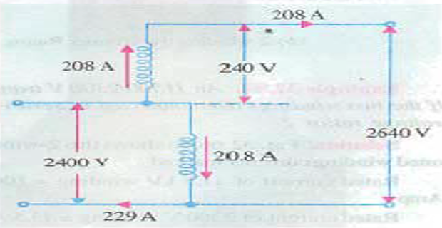
The output rating. The series winding carries the output current, and it may carry no more than its rated 208 A:
Eleven times the two-winding rating, from the same iron and the same copper.
The input current, which must equal the output current plus the common-winding current:
So the common winding carries only 20.8 A — exactly its rated current, in the opposite direction to the through current.
At unity power factor the rated output is 550 kW. The inductively transferred part is the power handled by the windings themselves:
Both windings give the same 50 kW, and it is precisely the rated output of the machine as a two-winding transformer. Nothing more can pass through the magnetic circuit than the transformer was built for.
The rest travels conductively:
Ninety-one percent of the output never enters the magnetic circuit at all; it flows straight from the supply to the load through the common winding's conductor. The ratio \(2400/2640 = 0.909\) is that share exactly.
What has changed and what has not:
| Quantity | As two-winding | As autotransformer |
|---|---|---|
| Rating | 50 kVA | 550 kVA |
| Voltage ratio | 2400 / 240 | 2400 / 2640 |
| Winding currents | 20.8 A and 208 A | 20.8 A and 208 A — unchanged |
| Iron and copper loss | as designed | identical |
| Isolation | full | none |
Key Formulas
| Quantity | Relation | Notes |
|---|---|---|
| Ratio | \(a = N_1/N_2 = V_1/V_2 = I_2/I_1\) | Same as any transformer — every problem |
| Throughput | \(S = V_1I_1 = V_2I_2\) | 40 kVA in Problem 2, 550 kVA in Problem 4 |
| Common-winding current | \(I_{\text{common}} = \left|I_2 - I_1\right|\) | 20 A in Problem 2, 20.8 A in Problem 4 |
| Series-winding voltage | \(V_{\text{series}} = \left|V_1 - V_2\right|\) | 100 V in Problem 2, 240 V in Problem 4 |
| Inductively transferred | \(P_{\text{ind}} = V_{\text{series}}I_{\text{series}} = V_{\text{common}}I_{\text{common}}\) | Equals the two-winding rating — Problems 1, 4 |
| Conductively transferred | \(P_{\text{cond}} = S - P_{\text{ind}} = S\,V_{LV}/V_{HV}\) | 1.5 kW in Problem 1, 500 kW in Problem 4 |
| Step-down split | \(P_{\text{cond}} = S/a,\quad P_{\text{ind}} = S(1 - 1/a)\) | \(a = 2\) gives an even split — Problem 1 |
| Copper weight ratio | \(W_{\text{auto}}/W_{\text{2-w}} = 1 - V_{LV}/V_{HV}\) | 0.2 in Problem 2 |
| Copper saving | \(\text{saving} = V_{LV}/V_{HV}\) | 80% in Problem 2 |
| Uprating on reconnection | \(S_{\text{auto}} = S_{\text{2-w}}\dfrac{V_{HV}}{V_{HV} - V_{LV}}\) | ×2 in Problem 3, ×11 in Problem 4 |
| Copper loss scaling | \(P_{cu} \propto I_{\text{winding}}^2\) | Quarter loss at half winding current — Problem 3 |
| Iron loss | \(P_i\) unchanged by reconnection | Same volts per turn, same flux — Problem 3 |
| Efficiency | \(\eta = \dfrac{P_{\text{out}}}{P_{\text{out}} + P_i + P_{cu}}\) | 95% becomes 97.98% — Problem 3 |
| Input current | \(I_{HV} = P_{\text{in}}/V_{HV}\) | Uses the input power, losses included — Problem 3 |
Common Mistakes
Giving the common winding the full load current. It carries the difference of the two line currents: 20 A, not 100 A, in Problem 2.
Swapping the conductive and inductive shares. The inductive part is the smaller one whenever the ratio is near unity — 50 kW out of 550 kW in Problem 4. Problem 1 hides the error because the two happen to be equal at \(a = 2\).
Assuming a reconnected transformer keeps its kVA. The 50 kVA unit of Problem 4 becomes a 550 kVA autotransformer, and the 5 kVA unit of Problem 3 becomes 10 kVA.
Scaling the losses with the new rating. They do not move. In Problem 3 the iron loss stays at 50 W because the volts per turn are unchanged, and the copper loss follows the winding current only.
Computing the high-voltage current from the output power. Problem 3 needs \(5103/220\), not \(5000/220\) — the input carries the losses too.
Sizing the windings on the throughput. The windings of Problem 2 are built for 8 kVA while 40 kVA passes through the terminals; using 40 kVA would size the copper five times too heavily.
Expecting a large ratio to give a large saving. The saving is \(V_{LV}/V_{HV}\), so it collapses as the ratio grows: 80% at 500/400 V but only 10% at 10 : 1.
Forgetting that the isolation is gone. A break in the common winding puts the full input voltage across the load. This, not the arithmetic, is why autotransformers are barred from many applications.
Ignoring the reduced per-unit impedance. The uprating of Problem 4 divides the per-unit impedance by 11 and multiplies the prospective short-circuit current accordingly.
The autotransformer is the first machine in this book that is not two separate circuits. Removing the isolation let the same iron and copper carry several times the power, and every result on this page — the current in the common winding, the copper saving, the uprating factor — turned out to be one ratio, \(V_{LV}/V_{HV}\), wearing different clothes.
Everything so far has also been single phase. Power is generated, transmitted and consumed in three, and a three-phase transformer is more than three single-phase units bolted together: the way the windings are grouped decides the line-to-phase relations, the phase shift between primary and secondary, and whether third-harmonic currents have a path to circulate in.
Next: Set 23 — Three-Phase Transformers and Connections, where star, delta and open-delta banks are worked through and the vector groups are given their meaning.