Set 11 — DC Motors — Back EMF, Torque and Speed
A dc motor is a dc generator with the current reversed. The armature still induces an emf as it turns, but now that emf opposes the supply, and the difference between the two — a few volts across a fraction of an ohm — sets the armature current, the torque and the speed together. This set works that idea in both directions: from voltage and flux to speed, and from current and flux to torque.
The problems run from a machine operated first as a generator and then as a motor, through gross and shaft torque for lap and wave armatures, to efficiency inferred from a single light-load reading and a series motor whose flux collapses with its load.
A motor generates too. The rotating armature induces the same emf as a generator would, and it opposes the supply. Everything on this page follows from that one sign change:
\[ E_a = V_t - I_aR_a \quad\text{(motor)}, \qquad E_a = V_t + I_aR_a \quad\text{(generator)} \]The field current changes sides as well. A shunt motor draws \(I_L\) from the mains and splits it, so \(I_a = I_L - I_f\); a shunt generator's armature supplies both load and field, so \(I_a = I_L + I_f\).
The emf equation is unchanged and is what converts \(E_a\) into speed:
\[ E_a = \frac{\phi Z N}{60}\times\frac{P}{A} \]Gross torque comes from the developed power. All of \(E_aI_a\) becomes mechanical, so \(T_a\omega_m = E_aI_a\), and substituting the emf equation removes the speed altogether:
\[ T_a = \frac{E_aI_a}{\omega_m} = \frac{1}{2\pi}\,\phi ZI_a\frac{P}{A} = 0.159\,\phi ZI_a\frac{P}{A}\ \text{N·m} \]Shaft torque is smaller than gross torque by the rotational losses: \(T_{sh} = P_{\text{out}}/\omega_m\), and \(T_a - T_{sh}\) is the lost torque.
Two operating points, one ratio. Comparing any two conditions of the same machine kills the constants:
\[ \frac{N_2}{N_1} = \frac{E_{a2}}{E_{a1}}\times\frac{\phi_1}{\phi_2} \]In a series motor the armature current is the field current, so \(E_a = V_t - I_a(R_a+R_{se})\) and the flux changes with load. Speed and current are never independent in such a machine.
A 25 kW, 250 V dc shunt machine has armature and field resistances of 0.06 Ω and 100 Ω respectively. Determine the total power developed in the armature when the machine works
- as a generator delivering 25 kW output
- as a motor taking 25 kW input
The line current is 100 A in both cases, but it flows the other way. The 25 kW is an output in (a) and an input in (b), and at 250 V either gives
The field current is the same in both cases too, because the field is across 250 V either way: \(I_f = 250/100 = 2.5\ \text{A}\).
As a generator, the armature feeds the load and the field. Both currents leave the armature, so they add:
Power developed in the armature is the emf times the armature current:
More than the 25 kW delivered, and by exactly the right amount: 630 W of armature copper loss plus 625 W of shunt field loss make up the difference.
As a motor, the line current splits at the terminals. The field is a shunt path, so the armature receives what is left:
The developed power follows the same product:
Less than the 25 kW drawn, again by the sum of the two copper losses — 570 W in the armature and 625 W in the field.
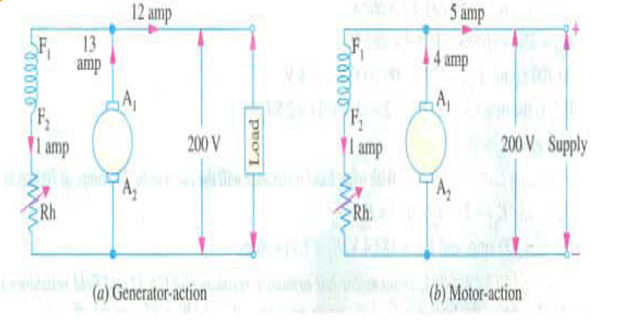
A 4-pole, lap-wound dc shunt generator with 32 armature conductors delivers 12 A to a load at a terminal voltage of 200 V when driven at 1000 rpm. Its armature resistance is 2 Ω and its field resistance 200 Ω.
- Calculate the flux per pole in the machine.
- The same machine is now run as a motor from the same 200 V supply, drawing 5 A from the mains with the magnetic field unchanged. Find its speed.
As a generator, add the field current to the load current. The shunt field is across the 200 V terminals:
The generated emf exceeds the terminal voltage:
Invert the emf equation for the flux. Lap winding, so \(A = P\) and the pole factor cancels:
The figure is large for a real pole because the stated conductor count of 32 is a textbook simplification; the method is unaffected, and the same flux is carried through part (b).
As a motor the field current is unchanged — same supply, same field resistance — but it is now drawn from the mains alongside the armature current:
The back emf is below the supply:
The flux is the same, so speed follows the emf directly. Rather than re-substituting into the emf equation, take the ratio of the two conditions:
Substituting \(\phi = 0.42375\ \text{Wb}\) back into \(N = 60E_a/(\phi Z)\) gives the same 849.6 rpm, at the cost of more arithmetic.
A dc motor takes an armature current of 110 A at 480 V. The armature circuit resistance is 0.2 Ω. The machine has 6 poles and its armature is lap-connected with 864 conductors. The flux per pole is 0.05 Wb. Calculate
- the speed
- the gross torque developed by the armature
Back emf first — it is the only quantity that carries the speed. The armature current is given directly, so no field split is needed:
Solve the emf equation for \(N\). Lap-connected with 6 poles gives \(A = P = 6\), so \(P/A = 1\):
Gross torque needs no speed at all. Substituting the emf equation into \(T_a = E_aI_a/\omega_m\) cancels \(N\) and leaves
Confirm it the long way. The developed power and the mechanical speed give the same torque:
Agreement here is a genuine check: the two routes use the emf equation in opposite directions, so a slip in \(\phi\), \(Z\) or \(P/A\) would show up as a mismatch.
A 220 V, 4-pole series motor has 800 conductors wave-connected on its armature. It supplies a load of 8.2 kW while taking 45 A from the mains. The flux per pole is 25 mWb and the armature circuit resistance is 0.6 Ω. Determine the developed torque and the shaft torque.
In a series motor the line current is the armature current — there is no parallel field path — so \(I_a = 45\ \text{A}\). Wave-connected means \(A = 2\), so \(P/A = 2\). The developed (gross, or armature) torque follows at once:
"Developed torque", "gross torque" and "armature torque" are three names for this one quantity.
Back emf, from the supply less the armature-circuit drop:
The 0.6 Ω already covers armature and series field together, as "armature circuit resistance" always does.
Speed, worked in rev/s to suit the power calculation. Writing the emf equation with \(n\) in rev/s drops the 60:
Shaft torque comes from the output, not from the flux. The 8.2 kW is what leaves the shaft:
The gap between the two torques is the rotational loss. Checking it closes the problem:
The 485 W of iron and friction loss appears identically as a power difference and as a torque difference, which it must if the speed used in both is the same.
A 500 V dc shunt motor draws a line current of 5 A on light load. Its armature resistance is 0.15 Ω and its field resistance 200 Ω. Determine the efficiency of the same machine running as a generator and delivering a load current of 40 A at 500 V.
The light-load run is a measurement, not a distraction. Its only purpose is to find the constant losses — core loss and friction — which cannot be calculated from resistances. Running unloaded as a motor, the machine draws
Strip out the copper losses from that input. The field takes
leaving \(I_a = 5 - 2.5 = 2.5\ \text{A}\) in the armature and an armature copper loss of only \(2.5^2 \times 0.15 = 0.94\ \text{W}\), which is negligible at this scale.
What remains is the constant loss. The unloaded machine does no useful work, so everything not dissipated in copper is spent on iron and friction:
This figure holds at rated speed and rated flux whatever the load, which is what makes a single no-load reading enough to predict efficiency at any load.
Now switch the machine to generating. Delivering 40 A at 500 V:
Note the sign: as a generator the armature carries the field current as well, so it is 42.5 A and not 37.5 A.
Assemble the losses at this load:
Efficiency, output over output plus losses:
The input need never be measured — which is the point of the method, since driving a 20 kW generator to measure its input directly requires a calibrated 23 kW prime mover.
A dc series motor runs at 800 rpm with a line current of 100 A from 230 V mains. Its armature circuit resistance is 0.15 Ω and its field resistance 0.1 Ω. Find the speed at which the motor runs when the line current falls to 25 A, assuming the flux at that current is 45% of the flux at 100 A.
Write the two-condition speed relation and note that in a series motor both factors change with load:
The flux ratio is given: \(\phi_2 = 0.45\phi_1\), so \(\phi_1/\phi_2 = 1/0.45 = 2.222\). The saturation implied by that figure is why the flux is not simply proportional to the current.
The armature current is the line current, and it passes through armature and field alike, so the total series resistance is \(0.15 + 0.1 = 0.25\ \Omega\):
The back emf rises only 9% as the load falls, because the total series resistance is small. The flux, by contrast, falls to 45%.
Combine the two effects:
Almost the whole of the 2.4-fold speed rise comes from the collapsing flux; the emf ratio contributes barely a tenth of it.
Key Formulas
| Quantity | Relation | Notes |
|---|---|---|
| Back emf, motor | \(E_a = V_t - I_aR_a\) | Problems 1–4, 6 |
| Generated emf, generator | \(E_a = V_t + I_aR_a\) | Problems 1, 2, 5 |
| EMF equation | \(E_a = \dfrac{\phi ZN}{60}\times\dfrac{P}{A}\) | \(N\) in rpm — Problems 2, 3 |
| EMF equation, rev/s | \(E_a = \phi Zn\dfrac{P}{A}\) | Drop the 60 — Problem 4 |
| Shunt motor current | \(I_a = I_L - I_f\) | Problems 1, 2 |
| Shunt generator current | \(I_a = I_L + I_f\) | Problems 1, 2, 5 |
| Series motor current | \(I_a = I_L\), \(E_a = V_t - I_a(R_a+R_{se})\) | Problems 4, 6 |
| Power developed | \(P_{\text{dev}} = E_aI_a\) | Problems 1, 4 |
| Gross torque | \(T_a = \dfrac{1}{2\pi}\phi ZI_a\dfrac{P}{A} = 0.159\,\phi ZI_a\dfrac{P}{A}\) | N·m — Problems 3, 4 |
| Torque from power | \(T_a = E_aI_a/\omega_m,\ \omega_m = 2\pi N/60\) | Cross-check — Problem 3 |
| Shaft torque | \(T_{sh} = P_{\text{out}}/\omega_m\) | Problem 4 |
| Lost torque | \(T_a - T_{sh} = P_{\text{rot}}/\omega_m\) | Iron plus friction — Problem 4 |
| Speed ratio | \(\dfrac{N_2}{N_1} = \dfrac{E_{a2}}{E_{a1}}\times\dfrac{\phi_1}{\phi_2}\) | Problems 2, 6 |
| Constant losses | \(P_0 = P_{\text{in},0} - V_tI_f - I_{a0}^2R_a\) | From no-load test — Problem 5 |
| Efficiency | \(\eta = \dfrac{P_{\text{out}}}{P_{\text{out}} + \sum\text{losses}}\) | Generator — Problem 5 |
Common Mistakes
Adding the field current to the line current in a motor. A shunt motor's line current splits between armature and field, so \(I_a = I_L - I_f\); only in a generator do they add — Problems 1, 2 and 5.
Quoting the rated power as the armature power. The 25 kW is the terminal quantity; the armature develops \(E_aI_a\), which is 26.26 kW generating and 23.80 kW motoring — Problem 1.
Using \(V_t\) in place of \(E_a\) in the emf equation. Only the induced emf is proportional to \(\phi N\); the terminal voltage differs from it by the armature drop — Problems 2 and 3.
Putting the line current into the torque formula. Torque is produced by the armature conductors, so it is \(I_a\) that appears — Problem 3.
Using \(A = P\) for a wave winding. Wave always gives \(A = 2\), and the resulting factor of \(P/2\) doubles the torque in a 4-pole machine — Problem 4.
Mixing rpm and rev/s in the same solution. \(2\pi nT = P\) needs rev/s while \(E_a = \phi ZNP/60A\) needs rpm; the factor of 60 gets lost between them — Problem 4.
Treating gross torque and shaft torque as the same quantity. They differ by the lost torque, 16 N·m out of 286 N·m here — Problem 4.
Counting the field copper loss as part of the constant loss. The no-load input contains both; subtract the field loss before calling the remainder iron plus friction, or it is counted twice — Problem 5.
Ignoring the series field resistance in a series motor. The armature current passes through it, so the drop is \(I_a(R_a+R_{se})\) — Problem 6.
Holding the flux constant in a series motor. Its field winding carries the load current, so the flux changes with every change of load and the ratio \(\phi_1/\phi_2\) can never be dropped from the speed relation — Problem 6.
Motoring turned out to require no new theory at all. The same emf equation, the same machine constant and the same power product served throughout; only two signs changed, and the second half of the set showed that torque and speed read the machine constant from opposite ends — torque from the current, speed from the voltage.
That separation is what makes the dc motor controllable. Because \(N \propto E_a/\phi\) and \(E_a = V_t - I_aR_a\), three independent handles present themselves: the flux, the armature-circuit resistance, and the applied voltage. Problem 6 has already shown how violently the first of them acts.
Next: Set 12 — Speed Control of DC Motors, where field weakening, armature-resistance control and voltage control are each worked at constant load torque, and the cost of each in current and efficiency is made explicit.