Demonstrative Video
SCOTT or T-T CONNECTIONS
\(3-\phi\) to \(2-\phi\) and vice versa
Proposed by Charles F. Scott
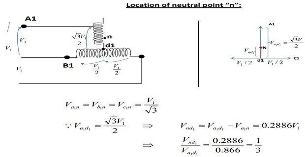
Main Transformer: Centre taps both on primary and secondary winding forms the horizontal member
Teaser Transformer: 0.866 tap. Its one end of the primary and secondary winding is joined to the centre taps on both primary and secondary of the main transformer, respectively.

The other end \(A_1\) of the teaser primary and the two ends \(B_1\) and \(C_1\) of the main transformer primary are connected to the 3-phase supply
Application of Scott Connection
Electric furnace installation where it is desired to operate two single-phase together and draw the balanced load from the three-phase supply.
Supply the single phase loads such as electric train which are so scheduled as to keep the load on the three phase system as nearly as possible.
Link a \(3-\phi\) system with a \(2-\phi\) system with the flow of power in either direction.
\(\checkmark\) The Scott-T connection permits conversions of a 3-phase system to a 2-phase system and vice versa. But since 2-phase generators are not available, the converters from two phases to three phases are not used in practice.

The two Transformers are connected electrically but not magnetically
Assume a 3-phase \(V_L = 100~V\) and \(K = 1\)

Scott Explain \(E_{DC}\) and \(E_{DB}\) differ by \(180^\circ\) because both coils are on the same magnetic circuit and are connected in opposition
Each side of the equilateral triangle represents 100 V
\(E_{DA} = (\sqrt{3}/2)\times 100=86.6~V\) and lags behind the voltage across the main by \(90^\circ\)
The same relation holds good in the secondary winding so that \(abc\) is a symmetrical 3-phase system
With reference to secondary voltage triangle for UPF load \(I_{db}\) lags \(E_{db}\) by \(30^\circ\) and \(I_{dc}\) leads \(E_{dc}\) by \(30^\circ\)
In other words, the teaser and each half of the main transformer, all operates at different power factors
Obviously, the full rating of the transformers is not being utilized
The teaser transformer operates at only 0.866 of its rated voltage
The main transformer coils operate at \(\cos 30^\circ = 0.866\) power factor, which is equivalent to the main transformers coils working at 86.6% of their KVA rating
Hence, the capacity to rating ratio in a T-T connection is 86.6%–the same as in V-V connection if two identical units are used