Demonstrative Video
Equivalent Circuit of an IM
2-winding Transformer:
\(I_0\) is 1% of the F.L Current
Reason: magnetic flux is confined completely in the steel core of low reluctance, hence \(I_\mu\) is small, as a result \(I_0\) is small
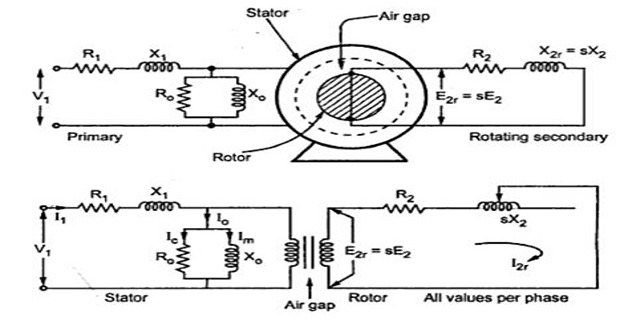
Induction Motor:
presence of air-gap (high reluctance) necessitates a large \(I_\mu\), hence \(I_0\) is very large (40-50 % of F.L Current)
Although, stator and rotor operates at different frequency, but represented in the same vector diagram because magnetic field relative to them are synchronous with each other
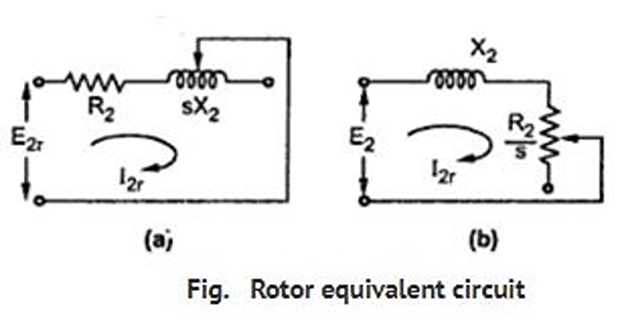
- When motor is loaded, rotor current is given by\[I_{2}=s\dfrac{E_{2}}{\sqrt{R_{2}^{2}+\left(sX_{2}\right)^{2}}}=\dfrac{E_{2}}{\sqrt{\left(R_{2}/s\right)^{2}+X_{2}^{2}}}\]
From above equation, rotor circuit consists of
a fixed \(R_2\) and variable \(sX_2\) (proportional to slip) connected across \(E_r = sE_2\), or
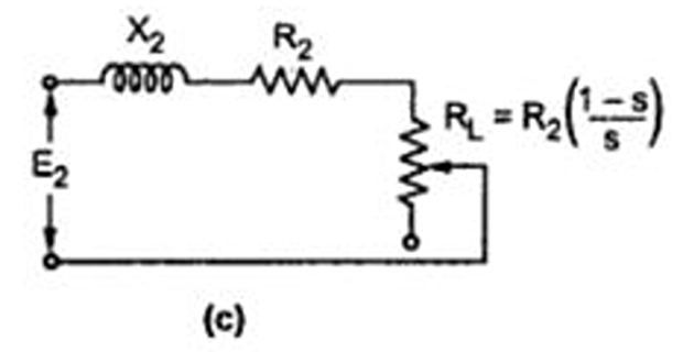
Fixed reactance \(X_2\) connected in series with a variable \(R_2/s\) (inversely proportional to slip) and supplied with constant \(E_2\)
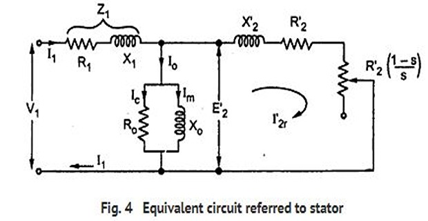
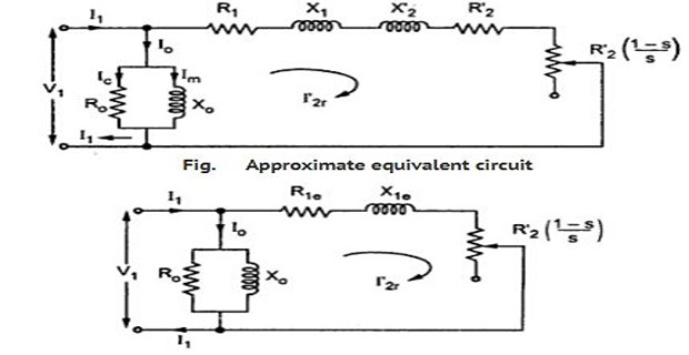
The exciting current may be transferred to the left because inaccuracy involved is negligible and calculations is very much simplified