Demonstrative Video
Torque Produced by \(1-\phi\) Induction Motor
Each component mmf wave induces motor action.
Torques from these waves oppose each other.
At rest, equal forward and backward flux waves yield no starting torque.
If these waves remain equal during rotor motion, torque-speed resembles a polyphase motor with low stator leakage impedance.
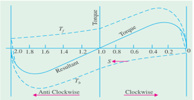
Resultant torque-speed characteristic is the sum of two component curves.
Slip varies \(0-2\)
At standstill, \(s=1\) and \(2-s = 1\)
\(T_f\) and \(T_b\) numerically equal but opposite direction
Hence, \(T_{st}=0\)
Motor, when started by auxiliary means, produces torque in the initiated direction.
Assumption of equal flux waves during rotor motion simplifies actual conditions.
Ignored factors: stator leakage impedance effects and Induced rotor currents not fully considered.
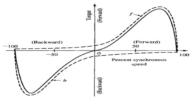
Rotor in motion increases backward rotor currents, reducing backward flux.
Forward field’s magnetic effect decreases as speed rises due to lower rotor currents.
Total flux waves remain constant, inducing a nearly constant stator counter emf.
Stator leakage-impedance voltage drop impact is minimized.
In motion, forward field torque surpasses backward field torque.
- Normal running region: forward field significantly greater than
backward field.
Spim 10 Flux wave resembles constant-amplitude polyphase motor’s air gap.
Single-phase motor’s torque-speed comparable to a polyphase motor.
Double-stator-frequency torque pulsations result from oppositely rotating flux waves.
Pulsations create no average torque but contribute to motor noise.
Torque on curves represents the time-averaged instantaneous torque.
Rotor Slip Due to Two Rotating Fields
Rotor is started by axillary means and torque developed
Forward field: direction of initial start
Let \(n_s = \text{synchronous speed} \quad n = \text{rotor speed}\)
- Slip of the motor w.r.t forward field\[s_f = s = \dfrac{n_s-n}{n_s} = 1- \dfrac{n}{n_s}\]
- Backward rotating flux rotates opposite to the stator, thus the corresponding back slip\[s_b = \dfrac{n_s-(-n)}{n_s} = 1+ \dfrac{n}{n_s}\]
- Adding both slips:\[s_f + s_b = 2~\quad \Rightarrow~s_b = \left(2-s_f\right)\]
Making Single-Phase IM Self-Starting
Motor is temporarily converted into a two-phase motor for self-starting.
- Stator has an additional starting winding alongside the main
winding.
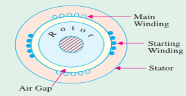
Spim 13 Two windings, spaced electrically \(90^{\circ}\) apart, are connected in parallel to a single-phase supply.
Ideal phase difference between the stator winding currents is \(90^{\circ}\).
The resulting currents create a revolving flux, ensuring self-starting of the motor.