Demonstrative Video
Types of Single Phase Induction Motors
A single-phase induction motor inherently is not self-starting.
To make it self-starting, some methods can be employed to produce a revolving magnetic field in the stator core.
This can be achieved by:
Converting a single-phase supply into two-phase supply.
Using an additional winding (which may or may not be disconnected once the motor starts and picks up speed).
Creating another field (by induction) using a short-circuiting band or ring.
Depending on the method used, single-phase induction motors can be classified as:
Split-phase Motors: Started by employing two-phase motor action through the use of an auxiliary winding called starting winding.
Capacitor Motors: Started by employing two-phase motor action through the use of an auxiliary winding with a capacitor.
Shaded-pole Motors: Started by the interaction of the field produced by a shading band or short-circuiting ring placed around a portion of the pole structure.
Split-Phase Machine:

Main Winding:
Responsible for continuous operation during normal running conditions.
Connected directly to the power supply with a relatively large number of turns of wire.
Starting Winding:
Another set of coils wound with fewer turns of wire than the main winding.
Electrically displaced from the main winding to create a phase difference for starting torque.
Starting Mechanism:
During startup, both windings are energized.
Phase difference between currents in main and starting windings creates a rotating magnetic field, providing starting torque.
Centrifugal Switch:
Prevents continuous current draw by the starting winding during normal operation.
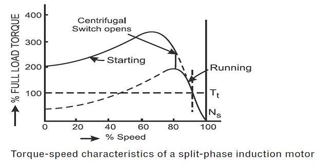
Activated by centrifugal force at a certain speed (around 70-80% of full speed).
Disconnects the starting winding from the power supply.
Running State:
After disconnection, the motor continues on single-phase power using only the main winding.
Main winding optimized for efficient operation under normal running conditions.
Applications:
Commonly used in applications requiring moderate starting torque, e.g., fans, blowers, and small tools.
Cost-effective solution for single-phase lighter starting loads.
Capacitor Motors:
It is also a split-phase motor, where a capacitor is connected in series with the starting winding.
This design represents an improved form of the traditional split-phase motor.
The angular displacement between \(I_S\) (starting current) and \(I_M\) (main current) can be made nearly \(90^\circ\).
High starting torques can be obtained because the starting torque is directly proportional to the sine of the angle \(\theta\).
The capacitor in the starting winding may be connected permanently or temporarily.
Capacitor motors may be classified as:
Capacitor Start Motors: Capacitor in the starting winding is used to provide a phase shift during startup for higher starting torque.
Capacitor Run Motors: Capacitor in the starting winding remains connected during the operation, improving efficiency and performance.
Capacitor Start and Capacitor Run Motors: Combines features of both capacitor start and capacitor run motors for optimized starting torque and continuous operation efficiency.
Capacitor start motors:
In the capacitor start induction motor, a capacitor \(C\) is of a large value to ensure high starting torque.
The torque \(T \times \sin\phi\), where \(\phi\) is the phase angle between \(I_M\) and \(I_S\), is significant in achieving high starting torque.
The capacitor employed is of short time duty rating.
The capacitor used is of the electrolytic type.
Electrolytic capacitor \(C\) is connected in series with the starting winding along with a centrifugal switch \(S\) .
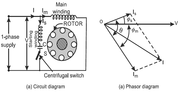
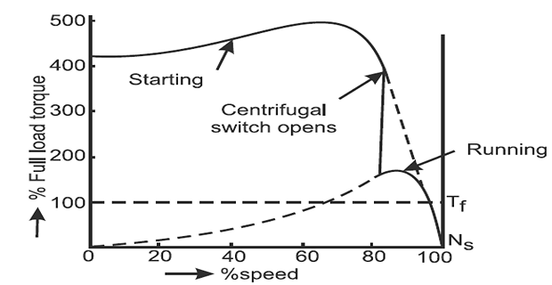
When the motor attains a speed of about 75% of synchronous speed, the starting winding is cutoff.
The construction of the motor and winding is similar to the usual split-phase motor.
Used in applications where high starting torque is required, such as in refrigerators.
The speed of the capacitor start induction motor is almost constant within a 5% slip.
This type of motor develops high starting torque, approximately 4 to 5 times the full load torque.
It draws low starting current, which is beneficial for efficient operation.
The direction of rotation can be changed by interchanging the connection of either the starting or running winding.
Capacitor run motors (fan motors)::
A paper capacitor is permanently connected in the starting winding.
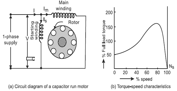
An electrolytic capacitor cannot be used because it is designed only for a short-time rating and cannot be permanently connected in the winding.
Both the main and starting winding are of equal rating.
Performance and Characteristics:
Starting Torque: Lower, about 50 to 100% of full load torque.
Power Factor: Improved, possibly approaching unity.
Efficiency: Improved to about 75
Applications: Usually used in fans, room coolers, portable tools, and other domestic and commercial electrical appliances.
Capacitor start and capacitor run motors:
Two capacitors are used: one for starting purpose and the other for running purpose.

For starting, an electrolytic type capacitor (\(C_s\)) is used, which is disconnected from the supply when the motor attains 75% of synchronous speed, assisted by a centrifugal switch \(S\).
For running, a paper capacitor (\(C_R\)) is used, which remains in the circuit of the starting winding during running conditions.
The \(C_s\) is of a higher value than that of \(C_R\).
Performance and Characteristics:
Operate as two-phase motors, providing the best performance and noiseless operation.
Starting Torque: High.
Starting Current: Low.
Provide better efficiency and higher power factor.
The only disadvantage is the high cost.
Shaded pole induction motor:
Constructed with salient poles in the stator, where each pole has its own exciting winding.
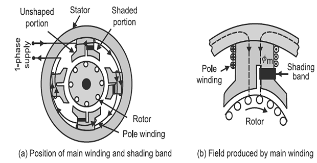
A 1/3rd portion of each pole core is surrounded by a copper strip forming a closed loop called the shading band.
The rotor is usually of the squirrel cage type.
When a single-phase supply is given to the stator (exciting) winding, it produces an alternating flux.
When the flux is increasing in the pole, a portion of the flux attempts to pass through the shaded portion of the pole, inducing an emf and current in the shading band or copper ring.
According to Lenz’s law, the direction of this current opposes the cause that produces it, i.e., the increase of flux in the shaded portion.
Initially, the greater portion of flux passes through the unshaded side of each pole, and the resultant lies on the unshaded side.
When the flux reaches its maximum value, its rate of change is zero, and the emf and current in the shading coil become zero.
Flux is uniformly distributed over the pole face, and the resultant field lies at the center of the pole.
After this, as the main flux tends to decrease, the emf and current induced in the shading coil now tend to increase the flux on the shaded portion of the pole, and the resultant lies on the shaded portion.
A revolving field is set up, rotating from the unshaded portion to the shaded portion, creating a starting torque in the rotor, causing it to start rotating.

Performance and Characteristics:
Starting Torque: Very small, about 50% of full load torque.
Efficiency: Low due to continuous power loss in the shading coil.
Used for small fans, electric clocks, gramophones, etc.
Direction of rotation depends on the position of the shading coil, from unshaded to shaded portion.
Direction of rotation cannot be reversed unless the position of the poles is reversed.