Demonstrative Video
Operation of Salient-Pole Machine
\(\Rightarrow\) uniform air-gap \(\Rightarrow\) reactance remains the same irrespective of the spatial position of the rotor \(\Rightarrow\) possess one axis of symmetry (pole or direct axis)
\(\Rightarrow\) non-uniform air-gap \(\Rightarrow\) reactance varies \(\Rightarrow\) two axes
field pole axis (direct or d-axis)
axis passing through center of inter-polar space (quadrature or q-axis)
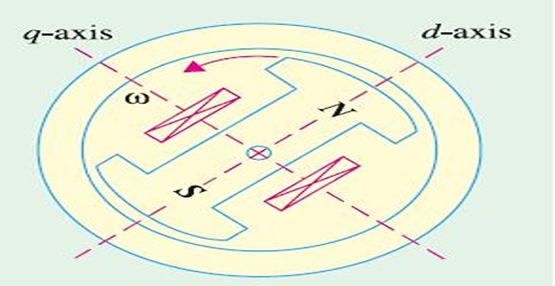
d-axis \(\Rightarrow\) Both field and armature mmfs
q-axis \(\Rightarrow\) Only armature mmf
Two-Reaction Theory (proposed by Blondel)
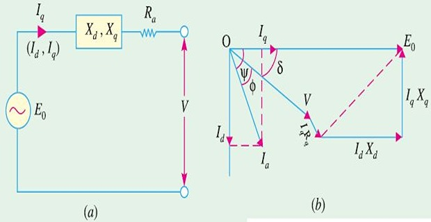
\(I_a \Rightarrow\) \(\left[I_d \perp E_0\right]\) and \(\left[I_q ~ \mbox{along} ~ E_0\right]\)
armature reactance \(\Rightarrow\) q-axis (\(X_{ad}\)) associated with \(I_d\) and d-axis (\(X_{aq}\)) associated with \(I_q\)
- \(X_L\)\[\begin{array}{ccc} X_{d}=X_{ad}+X_{L} & \mbox{and} & X_{q}=X_{aq}+X_{L}\end{array}\]
q-axis reluctance higher owing to larger air-gap, \(X_d>X_q\)
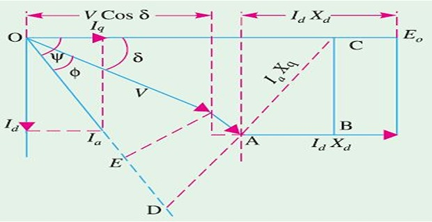
Power Developed by Syn Generator
- ): and hence Cu loss, per-phase power developed (Neglecting\[\begin{aligned} P_{d} & =VI_{a}\cos\Phi\\ I_{q}X_{q} & =V\sin\delta; ~~~ I_{d}X_{d}=E_{0}-V\cos\delta\\ I_d & = I_a\sin \left(\Phi + \delta \right); ~~~ I_q = I_a\cos \left(\Phi + \delta\right) \end{aligned}\]
- Substituting Eq. (3) in (1) and solving\[I_{a}\cos\phi=\dfrac{V}{X_{d}}\sin\delta+\dfrac{V}{2X_{q}}\sin2\delta-\dfrac{V}{2X_{d}}\sin2\delta\]
- Finally, Substituting in Eq. (1), we get\[P_{d}=\dfrac{E_{0}V}{X_{d}}\sin\delta+\dfrac{V^{2}\left(X_{d}-X_{q}\right)}{2X_{d}X_{q}}\sin2\delta\]
The total power = \(3 \times P_d\)
\(P_d\) consists of power due to (first term) + (second term)
If \(X_d = X_q\), for cylindrical rotor, second term = 0, and the power is due to first
If no field excitation, \(E_0 =0\), then first term = 0, and power is due to second