Demonstrative Video
Production of Rotating Field
Stationary coils wound and supplied for \(2-\phi\) or \(3-\phi\), respectively produce a uniformly rotating (or revolving) magnetic flux of constant value
Consider two windings P and Q placed at \(90^\circ\) w.r.t each other
Exciting with \(2-\phi\) supply the flux produce is purely sinusoidal (assume)
Direction of the flux is assumed positive whereas its opposite side indicates negative values

Conclusion:
The magnitude of the resultant flux is constant and is equal to \(\Phi_m\) – the maximum flux due to either phase
The resultant flux rotates at synchronous speed by \(N_s=120f/P\) rpm


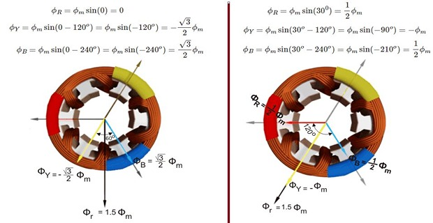

Conclusion:
The magnitude of the resultant flux is constant and is equal to \(1.5\Phi_m\) – the maximum flux due to either phase
The resultant flux rotates at synchronous speed by \(N_s=120f/P\) rpm
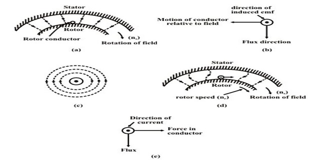
Why does the Rotor rotates?
The 3-phase supply given to the stator winding produce a magnetic flux of constant magnitude but rotating at synchronous speed
The flux passes through the air-gap, sweeps past the rotor surface and so cuts the rotor conductors which as yet are stationary
Due to the relative speed between the rotating flux and the stationary conductors, an emf is induced in the latter, according to Faraday’s laws of electro-magnetic induction
The frequency of the induced emf is the same as the supply frequency
Its magnitude is proportional to the relative velocity between the flux and the conductors and its direction is given by Fleming’s RHR
Since the rotor bars or conductors form a closed circuit, rotor current is produced whose direction is given by Lenz’s law, is such as to oppose the very cause producing it
In this case, the cause which produces the rotor current is the relative velocity between the rotating flux of the stator and stationary rotor conductors
Hence, to reduce the relative speed, the rotor starts running in the same direction as that of the flux and tries to catch up with the rotating flux
Assume stator field is rotating clockwise
The relative motion of the rotor w.r.t stator is anticlockwise
Thus by RHR, the induced emf in the rotor is outwards
Using LHR or combined effect, the rotor conductors experience a force tending to rotate them in clockwise
Thus, rotor is set into rotation in the same direction as that of the stator flux