Demonstrative Video
Methods of starting 3-\(\Phi\) IM
The purpose of starter:
To reduce the heavy starting current
To provide overload and under voltage protection.
The method employed in starting a IM depends upon the the size of the motor and the type of the motor.
The common methods used to start IMs are:
Direct-on-line starting
Stator resistance starting
Autotransformer starting
Star-delta starting
Methods (1) to (4) are applicable to all IMs
Method (4) is applicable only to slip ring (wound rotor)
In practice, any one of the four methods is used for starting squirrel cage motors, depending upon the size of the motor
But slip ring motors are invariably started by rotor resistance starting
Except DOL other three methods of starting squirrel-cage motors employ reduced voltage across motor terminals at starting
All methods of starting squirrel-cage control depends on applied voltage across the stator
Testing of Induction Motors
gives the information regarding no-load losses such as core loss, friction loss and windage loss
Rotor copper loss at no load is very less that its value is negligible
evaluate the resistance and impedance of the magnetizing path
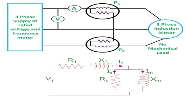
Friction and windage loss can be separated from \(P_0\)
At no load various readings of the No load loss are taken at the different stator applied voltages.
The readings are taken from rated to the breakdown value at rated frequency.
The curve is almost parabolic at the normal voltage.
As the iron losses are almost proportional to the square of the flux density and therefore, the applied voltage.
The curve is extended to the left to cut the vertical axis at the point A.
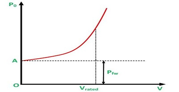
At the vertical axis \(V = 0\) and hence the intercept OA represents the independent voltage loss.
This means the friction and the windage losses are separated from the total no load loss.
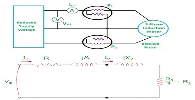
This test should be performed at the reduced frequency.
To obtain accurate results, Blocked Rotor Test is performed at a frequency 25 percent or less than the rated frequency.
The leakage reactances at the rated frequency are obtained by considering that the reactance is proportional to the frequency.
- and then some suitable test are done on stator windings to find the value of\[R_2 = R_{e1} - R_1\]