Demonstrative Video
An ideal transformer is one which has no losses, i.e. its windings have no ohmic resistance, there is no magnetic leakage, and hence has no \(I^2R\) and core losses
In other words, an ideal transformer consists of two purely inductive coils wound on a loss-free core
It is impossible to realize such a transformer in practice
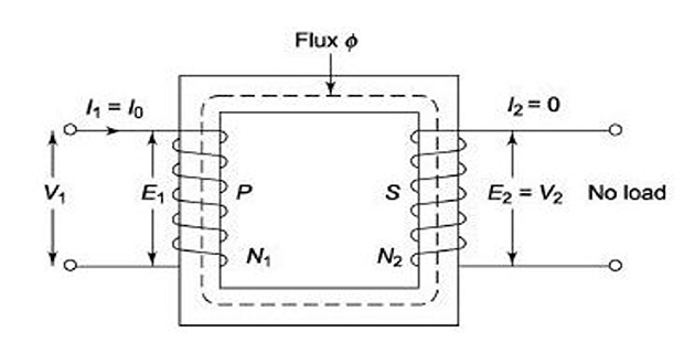
Consider an ideal transformer whose secondary is open and primary is connected to sinusoidal alternating voltage \(V_1\)
Potential difference cause an alternating current to flow in the primary
Since, the primary coil is purely inductive and the secondary is open (no output) the primary draws a magnetizing current \(I_\mu\) only
\(I_\mu\) is very small in magnitude, magnetize the core, and lags \(V_1\) by \(90^0\)
The alternating current \(I_\mu\) produces an alternating flux \(\Phi\), which at all times is proportional to the current and is in phase with it.

Ideal Transformer This changing flux is linked with both \(N_1\) and \(N_2\)
Therefore, it produced self induced emf in the primary (\(E_1\)) which at every instant oppose \(V_1\) known as counter emf or back emf of the primary
Similarly, there is secondary mutually induced emf (\(E_2\)), antiphase with \(V_1\)
The magnitude of \(E_2\) is proportional to the rate of change of flux and the number of secondary turns
Let,

Flux increases from zero to maximum value \(\Phi_{m}\) in one quarter of the cycle i.e. \(1/4~f\) s
\(\therefore\) Average rate of change of flux \(=\dfrac{\Phi_{m}}{1/4f}\) \(=4f\Phi_{m}\) volt Rate of change of flux per turn means induced emf in volts
\(\therefore\) Average emf/turn \(=4f\Phi_{m}\) volt If flux varies sinusoidally, then rms value of induced emf is obtained by multiplying the average value with form factor
Form factor = \(\dfrac{\mbox{r.m.s value}}{\mbox{average value}}\)= 1.11 \(\therefore\) r.m.s value of e.m.f/turn = \(1.11 \times 4f\Phi_{m} = 4.44f\Phi_{m} volt\) emf/turn is same for both the primary and secondary winding