By the end of this chapter you should be able to:
Identify the three variables in the speed equation that can be manipulated.
Calculate the resistance needed for a stated speed by armature control.
State the four disadvantages of armature resistance control and quantify the first.
Calculate the field weakening needed for a stated speed by flux control.
Compare the power wasted by the two methods.
Describe the diverter and tapped field methods for a series motor.
Explain why field control gives speeds above normal and armature control below.
Describe the Ward-Leonard method and state its range and cost.
The Three Handles
Chapter 34 gave the speed equation. Written out in full it exposes everything that can be adjusted:
Speed control of DC motors is therefore achieved by varying one of three quantities:
Insert resistance in the armature circuit. Reduces \(E_b\), so lowers the speed. Below normal only.
Weaken the field. Since \(N \propto 1/\Phi\), raises the speed. Above normal only.
Vary the supply to the armature. Gives speeds above and below normal, at the cost of extra equipment.
Armature Resistance Control — Shunt Motor
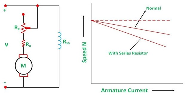
A variable resistance \(R_e\) is placed in series with the armature.
The variation in the variable resistance does not affect the flux, as the field is directly connected to the supply mains. The flux therefore stays at its full value, and only the numerator changes.
For a required speed \(N_2\) at the same load torque — and therefore, since \(\Phi\) is unchanged, the same \(I_a\):
Problem. A 230 V shunt motor with \(R_a = 0.30~\Omega\) runs at 1000 rev/min taking an armature current of 40 A. Find the resistance to be inserted to reduce the speed to 600 rev/min at the same load torque, and the power wasted in it.
Back EMF at 1000 rev/min.
Back EMF required at 600 rev/min. The flux is unchanged, so \(N \propto E_b\):
Resistance required. The torque is the same, so \(I_a\) is still 40 A:
Power wasted.
Compare the useful converted power.
Comment. The rheostat wastes 3.5 kW to deliver 5.2 kW — the armature-circuit efficiency has fallen to \(E_{b2}/V = 56.9\,\%\). Running at 60 % of rated speed costs 40 % of the armature input, dissipated as heat in a resistor.
The rule is general and easy to remember: at a fraction \(f\) of rated speed, roughly the fraction \((1 - f)\) of the armature input is wasted. Halving the speed throws away about half the power.
Armature Resistance Control — Series Motor
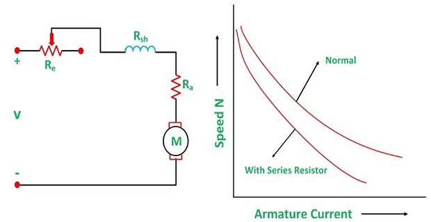
The arrangement is the same but the effect is not, because in a series motor the field carries the armature current.
By varying \(R_e\), both the current \(I\) and the flux \(\Phi\) are affected.
The voltage drop in the variable resistance reduces the voltage applied to the armature, and as a result the speed \(N\) falls.
When \(R_e\) is increased, the motor runs at a lower speed.
Since the variable resistance carries the full armature current, it must be designed to carry that current continuously.
Disadvantages of Armature Resistance Control
A large amount of power is wasted in the external resistance.
Restricted to keeping the speed below the normal speed of the motor; an increase above the normal level is not possible by this method.
For a given value of variable resistance, the speed reduction is not constant but varies with the motor load.
Used only for small motors.
The extra voltage dropped is \(I_aR_e\), and \(I_a\) depends on the load. At half load the drop is halved, so the speed falls only half as far — the setting that gives 600 rev/min at full load gives something quite different at part load.
This is a serious practical defect. A machine tool set to a slow cutting speed will speed up as the cut lightens, which is precisely when it should not. Example 37.2 puts numbers to it.
Problem. The rheostat of Example 37.1 is left at 2.180 \(\Omega\) and the load falls to half, so that \(I_a = 20\) A. Find the new speed, and compare with the speed the motor would run at without the rheostat at the same load.
With the rheostat, at 20 A.
Without the rheostat, at 20 A.
Comparison.
| Load | Speed without \(R_e\) | Speed with \(R_e\) | Reduction |
|---|---|---|---|
| Full, 40 A | 1000 rev/min | 600.0 rev/min | 400 rev/min |
| Half, 20 A | 1027.5 rev/min | 827.5 rev/min | 200 rev/min |
Comment. The same rheostat gives a 400 rev/min reduction at full load and only 200 rev/min at half load. The speed set at 600 rev/min has risen to 828 rev/min — a 38 % overshoot — simply because the load lightened.
Note that the drop is exactly proportional to \(I_a\), so the effect is not a subtlety but a direct consequence of Ohm's law. Any method that controls speed by dropping voltage across a resistance in series with a varying current has this defect.
Field Flux Control — Shunt Motor
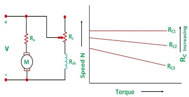
A variable resistance \(R_c\) — the shunt field regulator — is placed in series with the shunt field winding.
Above the normal speed the motor runs, because \(N \propto 1/\Phi\). Chapter 34's flux-weakening sequence explains the intermediate steps: the falling flux lowers \(E_b\), which raises \(I_a\) sharply, which raises the torque, which accelerates the motor.
The method is also used to correct the fall of speed caused by load. As a shunt motor droops a few percent from no load to full load, a small reduction of \(R_c\) restores the original speed — which is the basis of simple automatic speed regulators.
The two methods differ in what they hold constant, and this decides which loads they suit.
\(\Phi\) fixed, so a given \(I_a\) gives a given torque at any speed. Constant-torque drive — the available power falls with the speed.
\(I_a\) is limited by heating, so as \(\Phi\) falls the available torque falls in proportion while \(N\) rises. Constant-power drive.
A lathe wants constant power — small diameters need high speed and little torque, large diameters the reverse — which is why field control suits machine tools so well.
Problem. The motor of Example 37.1 has a shunt field of 115 \(\Omega\). Find the field-regulator resistance needed to raise the speed to 1300 rev/min at the same load torque, and the power wasted. Take the field as unsaturated, so \(\Phi \propto I_{sh}\).
Setting up. Let \(x = \Phi_2/\Phi_1\). At constant torque \(T \propto \Phi I_a\), so the current must rise:
The speed condition.
Solving.
Resulting current and back EMF.
Check: \((214.12/218)/0.7555 = 1.300\) \(\checkmark\)
The regulator. With \(\Phi \propto I_{sh}\), the field current must fall in the same ratio:
Power wasted in the regulator.
Comment. Compare with Example 37.1: 85 W against 3488 W, a factor of 41. Field control is efficient for the single reason that the shunt field carries a small current, so any resistance inserted there dissipates little.
Note the price paid elsewhere. The armature current has risen from 40 A to 52.9 A to maintain the torque at reduced flux, so the armature copper loss has risen by a factor of \((52.94/40)^{2} = 1.75\). Field weakening is efficient in the control element but loads the armature harder, which is why the speed range is limited by armature heating as much as by anything else.
Field Flux Control — Series Motor
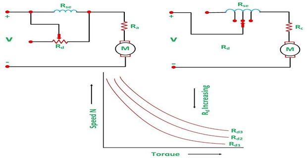
A series motor has no separate field circuit, so the flux is reduced by two other means.
A low resistance \(R_d\) is connected in parallel with the series field, so that part of the armature current bypasses it.
\(I_f\downarrow \Rightarrow \Phi\downarrow \Rightarrow N\uparrow\)
The ampere-turns are varied by varying \(N_{se}\) — tappings are brought out from the series winding and a selector switch chooses how many turns are in circuit.
Gives discrete speeds rather than continuous adjustment, but wastes nothing at all.
The diverter is the smoother method and the tapped field the more efficient. Neither wastes much power, because the diverter carries only part of the current and at a very low resistance, and the tapping wastes none.
Problem. A series motor has a field resistance of 0.10 \(\Omega\). Find the diverter resistance that reduces the field current to 70 % of the armature current, and estimate the resulting speed increase at constant armature current, assuming the field unsaturated.
Diverter resistance.
Speed effect. With the field unsaturated, \(\Phi \propto I_{se}\), so the flux falls to 70 % and
a speed increase of about 43 %, ignoring the small change in \(E_b\).
Comment. The diverter is 2.3 times the field resistance — a small value, and it carries 30 % of the armature current. Its loss is genuinely small: at 100 A armature current it dissipates \((30)^{2}(0.2333) = 210\) W, against the several kilowatts an armature rheostat would waste for a comparable speed change.
Note the direction. A diverter raises the speed, like all flux control. To lower a series motor's speed one must use armature resistance, or the series-parallel method used in traction, where two identical motors are switched from series to parallel to double the voltage on each.
Merits and Limits of Field Control
The method is easy and convenient.
As the shunt field current is very small, the power loss in the field regulator is also small.
It gives a constant-power drive, well suited to machine tools.
Flux cannot be increased beyond its normal value, because of the saturation of the iron.
Therefore speed control by flux is limited to weakening the field, which gives only an increase in speed.
Applicable over only a limited range, because if the field is weakened too much there is a loss of stability.
At very weak fields two things go wrong together. The armature current needed for a given torque becomes large, so the armature reaction of Chapter 30 becomes comparable with the main field — and armature reaction is itself demagnetising.
A small increase in load then weakens the flux further, which raises the speed further, which is the same runaway condition as the differential compound motor of Chapter 35. Beyond about 2:1 field weakening the machine becomes unmanageable, and 3:1 is an extreme limit even with compensating windings.
Commutation sets a second limit. Chapter 31's reactance voltage rises with \(I_a\) and with speed, and field weakening increases both at once.
Voltage Control — the Ward-Leonard Method
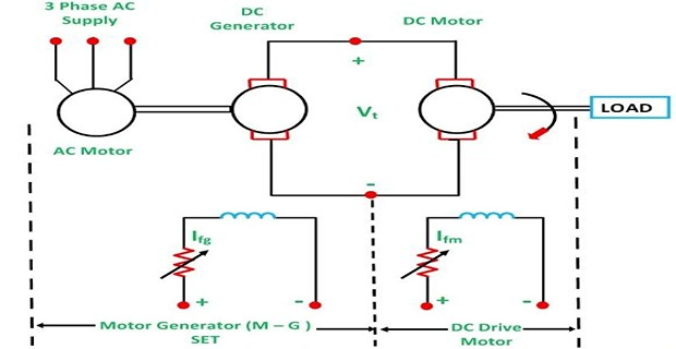
The third handle is the applied voltage \(V\). Since a DC supply of adjustable voltage is not generally available, one is generated on the spot.
- A driving motor — usually an AC induction motor — runs continuously at constant speed.
- It drives a separately excited DC generator, whose field is supplied through a rheostat and a reversing switch.
- The generator feeds the main motor directly, armature to armature. The main motor's field is separately excited at full strength.
Adjusting the generator field varies its output voltage from zero to full, and reversing that field reverses the main motor without any switching in the main circuit.
Very wide speed range, in both directions, from standstill upwards.
Control is smooth and stepless, with no resistance in the main circuit.
No power wasted in control resistances — only the small generator field current is controlled.
The main motor can be reversed and regeneratively braked simply by adjusting the generator field.
Three machines are needed instead of one — high capital cost and floor space.
Overall efficiency is low at light loads, since all three machines have their own losses.
More maintenance: three sets of bearings, brushes and commutators.
Noisy, and the driving set runs continuously whether or not the main motor is working.
The method was standard for rolling mills, mine winders, lifts and paper machines for most of the twentieth century. It has been almost entirely displaced by the thyristor or transistor converter, which produces the same adjustable DC voltage electronically — but the control principle is identical, and the name survives for the scheme.
Problem. A Ward-Leonard generator can be adjusted from 250 V down to 50 V. The main motor has \(R_a = 0.30~\Omega\) and draws 40 A at full load. Find the speed ratio available by voltage control alone, and the total range if field weakening of 1.3:1 is added at the top.
Back EMF at the extremes. At constant torque, \(I_a = 40\) A throughout:
Speed ratio by voltage alone. The flux is constant, so \(N \propto E_b\):
With field weakening added.
Comment. An 8:1 range in one direction, and the same again in reverse by reversing the generator field — a 16:1 span through zero, with no resistance in the main circuit anywhere.
Note how the two methods divide the work. Voltage control does everything below rated speed, where armature resistance would have wasted power; field control does everything above, where voltage control cannot go because the generator is already at full output. Each is used only in the region where it is efficient.
Note also that the range is not unlimited downward. At 50 V the armature drop of 12 V is nearly a quarter of the supply, so the speed regulation is poor; below about 20 V the motor would barely hold a load at all.
Comparison and Selection
| Armature resistance | Field flux | Ward-Leonard | |
|---|---|---|---|
| Speed range | Below normal only | Above normal only | Both, and reversal |
| Typical ratio | 3:1 down | 2:1 up | 8:1 or more |
| Power wasted | Large — 3488 W | Small — 85 W | Negligible in control |
| Speed with load | Varies badly | Nearly constant | Nearly constant |
| Drive character | Constant torque | Constant power | Either |
| Capital cost | Low | Low | High — three machines |
| Suited to | Small motors, intermittent duty | Machine tools, fans | Rolling mills, winders, lifts |
Summary and Key Formulas
From \(N \propto (V - I_aR_a)/\Phi\) the three handles are \(R_a\), \(\Phi\) and \(V\).
Armature resistance control inserts \(R_e\) in series with the armature. The flux is unaffected in a shunt motor because the field is across the mains; in a series motor both \(I\) and \(\Phi\) change.
Its four disadvantages: large power waste; speeds below normal only; speed reduction varies with load; used only for small motors.
Field flux control uses a shunt field regulator \(R_c\), with \(I_{sh} = V/(R_{sh} + R_c)\). Raising \(R_c\) weakens the flux and raises the speed above normal.
For a series motor the flux is reduced by a diverter in parallel with the field, or by tapped field control.
Field control is efficient because the field current is small, but is limited to weakening, and too much weakening causes loss of stability.
Armature control gives a constant-torque drive; field control a constant-power drive.
The Ward-Leonard method generates an adjustable voltage with a motor-generator set, giving a very wide range in both directions with no waste in the main circuit — at the cost of three machines.
| Quantity | Relation | Notes |
|---|---|---|
| Speed equation | \(N \propto \dfrac{V - I_aR_a}{\Phi}\) | the three handles |
| With armature rheostat | \(N \propto \dfrac{V - I_a(R_a + R_e)}{\Phi}\) | — |
| Rheostat required | \(R_e = \dfrac{V - E_{b2}}{I_a} - R_a\) | with \(E_{b2} = E_{b1}N_2/N_1\) |
| Power wasted | \(I_a^{2}R_e\) | large |
| Shunt field current | \(I_{sh} = \dfrac{V}{R_{sh} + R_c}\) | — |
| Field control sequence | \(R_c\uparrow \Rightarrow \Phi\downarrow \Rightarrow N\uparrow\) | above normal only |
| Constant-torque condition | \(I_{a2} = I_{a1}\dfrac{\Phi_1}{\Phi_2}\) | current rises as flux falls |
| Diverter | \(I_{se} = I_a\dfrac{R_d}{R_d + R_{se}}\) | series motor |
| Speed ratio, general | \(\dfrac{N_2}{N_1} = \dfrac{E_{b2}}{E_{b1}}\dfrac{\Phi_1}{\Phi_2}\) | use for every method |
Common Mistakes
Expecting field control to lower the speed. Strengthening the flux beyond normal is prevented by saturation, so field control only raises speed.
Expecting armature resistance to raise the speed. It can only drop voltage, so it only lowers speed.
Holding \(I_a\) constant when the flux changes. At constant torque \(I_a\) must rise as \(\Phi\) falls, which is why Example 37.3 needs a quadratic.
Forgetting to subtract \(R_a\). The rheostat is \((V - E_{b2})/I_a - R_a\).
Assuming the speed reduction is fixed once the rheostat is set. It is proportional to \(I_a\) and so varies with load.
Sizing an armature rheostat like a starter. A speed-control rheostat carries full current continuously.
Putting the diverter in series with the field. It goes in parallel, to bypass part of the current.
Believing field weakening is free. The regulator wastes little, but the armature current rises and its copper loss with the square.
Ignoring the stability limit. Beyond about 2:1 weakening, armature reaction makes the machine unmanageable.
Thinking Ward-Leonard needs no rheostat. It has one — in the generator field, where the current is small.
Chapter Review
Decide first whether the flux changes. If it does, the armature current changes too — unless the problem says otherwise.
P37.1 A 220 V shunt motor with \(R_a = 0.25~\Omega\) runs at 900 rev/min at \(I_a = 30\) A. Find the resistance to reduce the speed to 600 rev/min at the same torque.
Show answer
\[E_{b1} = 220 - 7.5 = 212.5~\mathrm{V}, \qquad E_{b2} = (212.5)\left(\frac{600}{900}\right) = 141.67~\mathrm{V}\]\[R_a + R_e = \frac{220 - 141.67}{30} = 2.611~\Omega, \qquad R_e = 2.361~\Omega\]P37.2 For P37.1, find the power wasted in \(R_e\) and the armature-circuit efficiency.
Show answer
\[P = (30)^{2}(2.361) = 2125~\mathrm{W}\]More than a third of the armature input is thrown away as heat.\[\eta_{\text{arm}} = \frac{E_{b2}}{V} = \frac{141.67}{220} = 64.4\,\%\]P37.3 With the rheostat of P37.1 still in circuit, the load halves so \(I_a = 15\) A. Find the new speed.
Show answer
\[E_b = 220 - (15)(2.611) = 220 - 39.17 = 180.83~\mathrm{V}\]Not 600 rev/min — the setting is only correct at the load it was set for.\[N = 900\left(\frac{180.83}{212.5}\right) = 765.9~\mathrm{rev/min}\]P37.4 A shunt motor runs at 1000 rev/min. By what factor must the flux be reduced to reach 1250 rev/min, if the back EMF is assumed unchanged?
Show answer
The flux must be reduced to 80 %. In reality \(E_b\) falls slightly as \(I_a\) rises, so a little more weakening is needed — as Example 37.3 showed.\[\frac{N_2}{N_1} = \frac{\Phi_1}{\Phi_2} = 1.25 \quad\Longrightarrow\quad \frac{\Phi_2}{\Phi_1} = 0.80\]P37.5 A 240 V shunt motor has a field of 120 \(\Omega\). Find the regulator resistance to reduce the field current to 80 % of normal, and the power it wastes.
Show answer
\[I_{sh1} = \frac{240}{120} = 2.00~\mathrm{A}, \qquad I_{sh2} = 1.60~\mathrm{A}\]\[R_{sh} + R_c = \frac{240}{1.60} = 150~\Omega \quad\Longrightarrow\quad R_c = 30~\Omega\]\[P = (1.60)^{2}(30) = 76.8~\mathrm{W}\]P37.6 A series motor has \(R_{se} = 0.08~\Omega\). Find the diverter for 60 % of the armature current in the field.
Show answer
\[\frac{R_d}{R_d + 0.08} = 0.60 \quad\Longrightarrow\quad 0.40R_d = 0.048\]The flux falls to 60 %, so the speed rises by roughly \(1/0.6 = 1.67\) times.\[R_d = 0.120~\Omega\]P37.7 Explain why armature resistance control gives a constant-torque drive and field control a constant-power drive.
Show answer
Armature control: the flux is unchanged, so a given armature current gives a given torque \(T = K_a\Phi I_a\) whatever the speed. The motor can deliver its full rated torque at any speed in the range — but since \(P = T\omega\), the available power falls in proportion to the speed. Constant torque.Field control: the armature current is limited by heating, and as \(\Phi\) falls the torque \(K_a\Phi I_a\) falls with it. But the speed rises in the same proportion, so \(T\omega\) stays roughly constant. Constant power.
A lathe wants constant power — a small workpiece needs high speed and low torque, a large one the reverse — which is why field control is the natural choice for machine tools.
P37.8 Why is field control so much more efficient than armature resistance control?
Show answer
Because of where the controlling resistance sits. The shunt field carries only a small current — typically 1 to 3 % of the armature current — so any resistance in that circuit dissipates \(I^{2}R\) with a very small \(I\).An armature rheostat carries the full armature current, so its loss is larger by the square of the current ratio.
Examples 37.1 and 37.3 gave 3488 W against 85 W — a factor of 41 for comparable speed changes on the same machine.
P37.9 Describe the Ward-Leonard system and state two advantages and two disadvantages.
Show answer
An AC motor drives a separately excited DC generator at constant speed. The generator feeds the main DC motor armature to armature, and its field is adjusted by a rheostat with a reversing switch. Varying the generator field varies its output voltage from zero to full; reversing it reverses the main motor.Advantages: very wide, stepless speed range in both directions from standstill; no power wasted in main-circuit resistance, since only the small generator field current is controlled. Regenerative braking comes free.
Disadvantages: three machines are needed, so capital cost, floor space and maintenance are all high; efficiency is poor at light load because all three machines carry their own losses.
P37.10 A drive must run from 200 to 1600 rev/min with 1000 rev/min as its natural speed. What combination would you use?
Show answer
Voltage control below 1000 rev/min, field control above it.200 to 1000: reduce the applied voltage. Armature resistance would give the range but would waste up to 80 % of the armature input at the bottom, and the speed would drift with load.
1000 to 1600: weaken the field, a 1.6:1 ratio, comfortably inside the stability limit of about 2:1.
Each method is used only where it is efficient, and between them they cover a range neither could manage alone. This is the standard arrangement for a rolling-mill or machine-tool drive.
MCQ 1. Speed control by armature resistance gives speeds:
(a) above normal (b) below normal (c) both (d) constantShow answer
(b) below normal, since resistance can only drop voltage.MCQ 2. In a shunt motor, an armature rheostat affects the flux:
(a) strongly (b) not at all (c) only at light load (d) only at heavy loadShow answer
(b) not at all — the field is connected directly across the supply mains.MCQ 3. A disadvantage of armature resistance control is that the speed reduction:
(a) is fixed (b) varies with load (c) is too small (d) reversesShow answer
(b) varies with load, because the drop \(I_aR_e\) is proportional to \(I_a\).MCQ 4. Field flux control gives speeds:
(a) above normal (b) below normal (c) both (d) neitherShow answer
(a) above normal, since the flux can only be weakened — saturation prevents increasing it.MCQ 5. Field control is efficient because:
(a) no resistance is used (b) the field current is small (c) the flux is constant (d) the speed is lowShow answer
(b) the field current is small, so the regulator's \(I^{2}R\) loss is small.MCQ 6. A diverter is connected:
(a) in series with the field (b) in parallel with the field (c) in series with the armature (d) across the supplyShow answer
(b) in parallel with the field, so part of the armature current bypasses it.MCQ 7. Tapped field control varies the:
(a) armature resistance (b) supply voltage (c) number of series turns (d) brush positionShow answer
(c) number of series turns, so the ampere-turns change without any resistance loss.MCQ 8. Excessive field weakening leads to:
(a) higher efficiency (b) loss of stability (c) lower current (d) better commutationShow answer
(b) loss of stability, because armature reaction becomes comparable with the weakened main field.MCQ 9. The Ward-Leonard method controls the:
(a) armature resistance (b) field flux (c) applied voltage (d) brush positionShow answer
(c) applied voltage, generated by a separately excited machine whose field is adjusted.MCQ 10. Armature control gives a drive of:
(a) constant torque (b) constant power (c) constant current (d) constant flux ratioShow answer
(a) constant torque. Field control gives constant power.
Derive the three methods of speed control from the speed equation.
Explain armature resistance control for shunt and for series motors, noting the difference.
State and explain the four disadvantages of armature resistance control.
Describe field flux control of a shunt motor and derive the effect on speed.
Describe the diverter and tapped field methods for a series motor.
Give the advantages and limitations of field control, explaining "loss of stability".
Describe the Ward-Leonard system with its advantages and disadvantages.
Explain the distinction between constant-torque and constant-power drives.
This chapter has been concerned with holding a motor at a chosen speed. Chapter 38 asks the opposite question: how to bring it — and its load — rapidly to rest. The answer in every case is to make the machine act as a generator, so that the kinetic energy of the load is converted back into electrical form instead of being ground away in a friction brake.
Three schemes do this. Rheostatic or dynamic braking dissipates the energy in a resistor; plugging reverses the supply for a very rapid stop at the cost of a heavy current; and regenerative braking returns the energy to the supply, which is why it appeared as a free benefit of the Ward-Leonard scheme in Section 37-8.
Chapter 39 then closes Part 2 with the testing of DC machines — the Swinburne, Hopkinson and retardation tests — which measure the losses of Chapter 33 and predict the efficiency without ever loading the machine to its full rating.