By the end of this chapter you should be able to:
Explain why a loop connected through slip rings delivers alternating current.
Explain how the split ring makes the external current unidirectional while the coil EMF stays alternating.
Describe the output waveform of a real machine with many coils and segments.
Connect armature coils to segments so that the two coil-side EMFs add.
Apply the two brush-location rules — meeting and separating points, and equal spacing opposite the poles.
Explain why brushes short-circuit coils and why this is harmless at the neutral axis.
Compute the commutation period from brush width, mica thickness and commutator speed.
Compute the reactance voltage and explain why it limits speed and current.
The Simple Loop with Slip Rings
Consider only one coil \(AB\) placed in a strong magnetic field.
The two ends of the coil are joined to slip rings.
Two brushes rest on these slip rings.
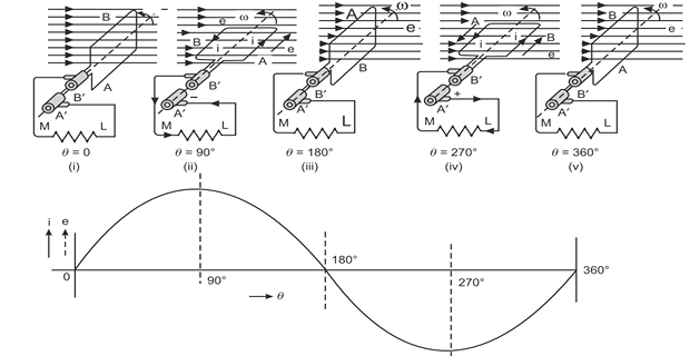
When the coil is rotated in the counter-clockwise direction at \(\omega\) radians per second, \(\phi\) is cut by the coil and an EMF is induced in it.
The induced EMF is alternating, and the current flowing through the external resistance is also alternating — that is, at the second instant current flows in the external resistance from \(M\) to \(L\), whereas at the fourth instant it flows from \(L\) to \(M\).
Commutator Action
Now consider that the two ends of the coil are connected to only one slip ring split into two parts — segments \(A''\) and \(B''\).
Each part is insulated from the other by a mica layer.
Two brushes rest on these parts of the ring.
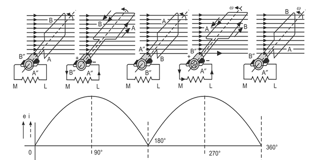
When the coil is rotated in the counter-clockwise direction at \(\omega\), \(\phi\) is cut and an EMF is induced in it. The magnitude of the EMF induced in the coil at the various instants remains the same as with slip rings.
However, the flow of current in the external resistor becomes unidirectional: at the second instant the current in the external resistor is from \(M\) to \(L\), and at the fourth instant it is again from \(M\) to \(L\).
AC is converted into unidirectional current in the external circuit with the help of the split ring — that is, the commutator.
The mechanism is worth stating plainly, because it is the whole of the DC machine in one line. The coil EMF reverses every half revolution, and so does the external connection. Two reversals cancel, and the load sees a constant polarity. The split occurs at the instant the coil EMF passes through zero, so the swap costs nothing.
Output of a Real Machine
In an actual machine there are a number of coils connected to a number of segments of the ring, called the commutator, and these coils deliver EMF and current to the external load.
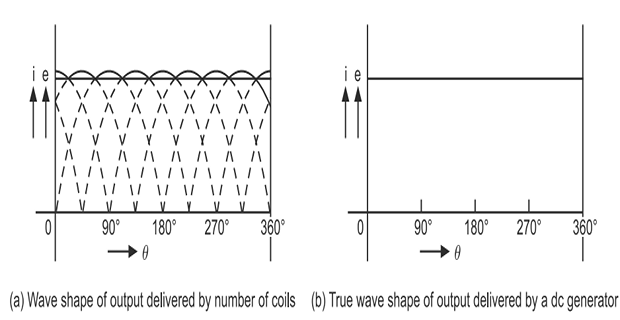
The actual current flowing in the external load is shown by the firm line, which fluctuates only slightly.
The number of coils placed on the armature is much greater than shown, and a practically pure direct current is obtained at the output.
In an actual machine working as a generator, the function of the commutator is to convert the alternating current produced in the armature into direct current in the external circuit.
Working as a motor, the same mechanism converts the alternating torque produced in the armature into unidirectional, continuous torque — which is Chapter 17's second answer to the unidirectional-torque problem.
Chapter 21 quantified the residual fluctuation: the ripple is \(1 - \cos(90^{\circ}/n)\) for \(n\) coils per pole pair, falling from 100 % with a single coil to under half a percent with sixteen. That is what "fluctuates only slightly" means numerically.
Connecting Coils to Segments
Consider an armature with four coils — 1, 2, 3 and 4 — equally spaced in slots. The number of commutator segments is equal to the number of coils.
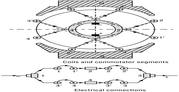
When the armature is rotated clockwise, the direction of the induced EMF — and hence the current — is:
in coil sides \(3', 1, 4', 2\)
in coil sides \(1', 3, 2', 4\)
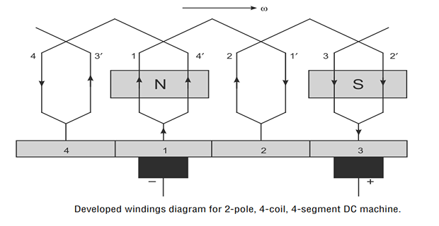
The coils should be connected in such a way that the EMFs induced in the two sides of the same coil add up.
Accordingly the coil sides \(1\text{-}4'\), \(1'\text{-}2\), \(2'\text{-}3\) and \(3'\text{-}4\) are connected to commutator segments 1, 2, 3 and 4 respectively.
This is the same requirement as the full-pitch condition of Chapter 19: the two sides of a coil must lie under opposite poles, one pole pitch apart, so that one carries current up while the other carries it down and their EMFs reinforce. Connect them the other way and the two EMFs would cancel exactly, giving a coil that generates nothing at all.
Locating the Brushes
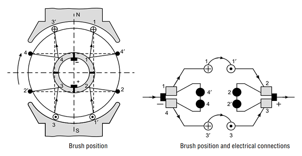
The next question is how many brush sets are required and where they are to be placed with respect to the poles. The brushes are to collect or deliver the current, and are placed at such a position that sparking is minimum.
The brushes at a meeting point are of positive polarity; those at a separating point are of negative polarity.
Applying the rule to the four-coil armature:
At segment 1, current is separated towards conductors 1 and \(4'\) — hence it is a separating point.
Current is coming towards segment 3 from conductors \(2'\) and 3 — hence it is a meeting point.
So commutator segment 1 is the position of the negative brush, and segment 3 the position of the positive brush.
For representation, the general convention is to place the brushes at the geometrical neutral plane (G.N.P.). All conductors above the brush axis then carry current in one direction and all conductors below it in the opposite direction.
This convention represents that the brushes are placed at the coil or coils in which the induced voltage is zero.
Problem. A 6-pole machine carries an armature current of 600 A. Find the number of brush sets and the current per set for (a) a lap winding and (b) a wave winding.
(a) Lap winding. The number of brush sets equals the number of parallel paths, which equals the number of poles:
(b) Wave winding. Only two parallel paths, whatever the pole count:
Comment. Each wave brush set carries three times the current, so it needs three times the contact area — which is why wave-wound machines have physically larger brushes but fewer of them. Note also that like-polarity brushes are connected together externally, so the machine still has just two terminals in both cases.
A wave winding can in fact be fitted with \(P\) brush sets rather than 2, which eases the current per brush; the winding still has only two paths, but the extra brushes tap them at additional points. This is common on large wave-wound machines.
Short-Circuited Coils
Rule (ii) brings out a very important point: in certain positions of the commutator the brushes will actually be short-circuiting the coils connected to the segments with which they are in contact.
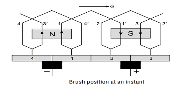
In the case illustrated, two coils are short-circuited, and as such the width of the brushes must be greater than the thickness of the mica insulation between segments.
The negative brush short-circuits segments 1 and 4, whereas the positive brush short-circuits segments 2 and 3.
Coils 4 and 2 are short-circuited by the brushes, and hence no EMF should be induced in these coils.
The armature winding forms a closed circuit and consists of two parallel paths.
When a coil undergoes commutation, no EMF is induced in it, since it passes through the magnetic neutral axis (MNA), and the coil is short-circuited by the brushes — hence no sparking will take place.
Short-circuiting a source of zero EMF drives no current. Short-circuiting a source of any appreciable EMF would drive a very large one, because the coil resistance is milliohms.
If the brush were narrower than the mica strip, there would be an instant when it touched neither segment. The armature circuit would be broken while carrying full current, and the inductance of the winding would force a violent arc — the same effect as opening a switch on an inductive load.
Making the brush wider guarantees that contact is transferred make-before-break. The short circuit is not an unfortunate side effect; it is deliberately arranged, and the whole design problem is to make sure it happens where the coil EMF is zero.
The Commutation Period
A coil stays short-circuited only briefly. The time for which it is so is the commutation period \(T_c\), and it follows directly from the geometry.
The brush must travel its own width, less the mica it started on, relative to the commutator surface:
with \(w_b\) the brush width, \(w_m\) the mica thickness, \(D_c\) the commutator diameter and \(N\) the speed in rev/min.
Two consequences follow immediately, and both matter for Chapter 31:
\(T_c \propto 1/N\) — the faster the machine runs, the less time there is to reverse the current.
\(T_c \propto w_b\) — a wider brush gives more time, but short-circuits more coils at once.
The number of coils short-circuited at any instant follows from the segment pitch:
Problem. A commutator is 250 mm in diameter and runs at 1000 rev/min. The brushes are 20 mm wide and the mica is 0.8 mm thick. Find the peripheral speed and the commutation period.
Peripheral speed.
Effective width travelled.
Commutation period.
Comment. A millisecond and a half. In that time the current in the coil must fall from its full value in one direction to its full value in the other. Everything difficult about DC machines happens inside this window — and Example 23.4 shows what it costs.
Note that a peripheral speed of 13 m/s is modest; large machines run at 30 m/s or more, which is close to the mechanical limit for a segmented copper cylinder held together by V-rings.
Problem. The commutator of Example 23.2 has 96 segments. How many coils does each brush short-circuit?
Segment pitch.
Segments bridged.
so the brush spans between two and three segment pitches, touching 3 segments at most positions.
Coils short-circuited. Adjacent segments are joined by one coil, so bridging 3 segments shorts
Comment. This is the trade-off named in Section 23-7. A wider brush lengthens \(T_c\), which helps the current reverse gently — but it also shorts more coils at once, and every one of them must be near the neutral axis for the short to be harmless. Since the neutral zone has finite width, there is a limit to how wide a brush can usefully be, and in practice it spans two to three segments.
The Reversal of Coil Current
Consider what the short-circuited coil must actually do. Before commutation it belongs to one parallel path and carries \(+I_a/A\); afterwards it belongs to the other path and carries \(-I_a/A\). The total change is
and it must happen within the commutation period \(T_c\).
The current falls at a constant rate, so the current density under the brush stays uniform across its whole face.
Nothing is left to interrupt at the trailing edge, and there is no spark.
Coil inductance delays the reversal. At the end of \(T_c\) the current has not finished reversing, and the remainder is interrupted as the brush leaves the segment.
The result is an arc at the trailing brush edge — visible sparking and rapid commutator burning.
This is the EMF the coil's own inductance generates in opposition to the change, by Chapter 13's \(e = L\,\mathrm{d}i/\mathrm{d}t\). It is what causes under-commutation, and it grows with both current and speed.
The remedies — shifting the brushes, adding interpoles, adding a compensating winding — are the subject of Chapter 31.
Problem. The machine of Example 23.2 is lap-wound with 4 poles and carries an armature current of 200 A. Each coil has an inductance of 0.040 mH. Find the reactance voltage.
Current per path.
Total change. The coil goes from \(+50\) A to \(-50\) A:
Rate of change. Using \(T_c = 1.467\) ms from Example 23.2:
Reactance voltage.
Comment. Under three volts — which sounds trivial until you remember what it acts on. The short-circuited coil has a resistance of a few milliohms, so 2.7 V across it would drive hundreds of amperes if nothing opposed it. What limits that current is the brush contact resistance of Chapter 22, which is precisely why carbon rather than copper is used.
Design practice keeps \(E_r\) below about 5 V without interpoles. Above that, an interpole must be fitted to generate an equal and opposite EMF in the commutating coil — the remedy developed in Chapter 31.
Why Commutation Limits the Machine
Collecting the results of this chapter shows why the commutator, and not the magnetics, sets the ceiling on a DC machine.
| Increase | Effect on \(E_r\) | Why it is hard to avoid |
|---|---|---|
| Armature current \(I_a\) | ∝ \(I_a\) | It is the machine's output |
| Speed \(N\) | ∝ \(N\) | It is the machine's output |
| Commutator diameter | ∝ \(D_c\) | Set by the number of segments needed |
| Coil inductance \(L\) | ∝ \(L\) | Set by turns per coil and slot geometry |
| Brush width \(w_b\) | ∝ \(1/w_b\) — helps | But shorts more coils at once |
| Parallel paths \(A\) | ∝ \(1/A\) — helps | Lap winding, but needs more brushes |
Problem. The machine of Examples 23.2 and 23.4 is to run at 1500 rev/min instead of 1000. Find the new commutation period and reactance voltage, and comment.
New peripheral speed.
New commutation period.
New reactance voltage.
Ratios.
Comment. Both scale exactly with speed, as the formulas require: \(T_c \propto 1/N\) and therefore \(E_r \propto N\). Raising the speed by half has raised the reactance voltage by half, to 4.09 V — approaching the 5 V limit at which interpoles become necessary.
This is why DC machines are not simply run faster to get more power out of the same frame, as Chapter 18's sizing equation would otherwise suggest. The \(D^{2}l\) rule says power rises with speed; commutation says the brushes will not stand it. For a DC machine the sizing equation is not the binding constraint.
Summary and Key Formulas
A coil connected through slip rings delivers alternating current — the machine is an alternator.
Replacing them by one ring split into two segments, insulated by mica, leaves the coil EMF unchanged in magnitude but makes the external current unidirectional.
In a real machine many coils feed many segments, and the output fluctuates only slightly — practically pure DC.
The function of the commutator is to convert the armature's AC into DC in the external circuit (generator), or the alternating torque into continuous torque (motor).
Coils are connected so that the EMFs of their two sides add, and the number of segments equals the number of coils.
Rule (i): place a brush at each meeting point (positive) or separating point (negative) of two EMFs. Rule (ii): brushes are equally spaced, opposite the pole centres, conventionally at the G.N.P.
Brushes short-circuit the coils they bridge. This is harmless because those coils are at the magnetic neutral axis where no EMF is induced — and the brush must be wider than the mica so that contact transfers make-before-break.
The commutation period is \(T_c = (w_b - w_m)/V_c\), typically one or two milliseconds, and varies as \(1/N\).
In that time the coil current must reverse from \(+I_a/A\) to \(-I_a/A\). Coil inductance opposes this, producing a reactance voltage \(E_r = L\,\Delta I/T_c\) which causes under-commutation and sparking.
\(E_r\) grows with both current and speed, which is why commutation — not the magnetic circuit — caps a DC machine's power.
| Quantity | Formula | Notes |
|---|---|---|
| Commutator peripheral speed | \(V_c = \dfrac{\pi D_cN}{60}\) | up to about 30 m/s |
| Commutation period | \(T_c = \dfrac{w_b - w_m}{V_c}\) | 1–2 ms typically |
| Segment pitch | \(\pi D_c/C\) | \(C\) = segments = coils |
| Segments bridged | \(w_b/\text{pitch} + 1\) | rounded down |
| Coils short-circuited | segments bridged \(- 1\) | usually 1–2 |
| Current per path | \(I_a/A\) | — |
| Current reversal | \(\Delta I = 2I_a/A\) | full swing, both directions |
| Reactance voltage | \(E_r = L\dfrac{2I_a}{A\,T_c}\) | keep below ~5 V |
| Brush sets | \(P\) for lap, 2 for wave | half positive, half negative |
| Current per brush set | \(I_a/A\) | — |
| Scaling | \(T_c \propto 1/N\), \(E_r \propto N I_a\) | the binding constraint |
Common Mistakes
Saying the commutator makes the coil EMF direct. It does not. The coil EMF stays alternating and unchanged in magnitude; only the external connection is switched.
Confusing slip rings with a split ring. Two separate rings give AC; one ring split in two gives DC.
Thinking the short-circuiting of coils is a fault. It is deliberate and unavoidable, and harmless provided it happens at the neutral axis.
Making the brush narrower than the mica. That would break the armature circuit under full current and cause a violent arc.
Taking the current change as \(I_a/A\). It is \(2I_a/A\), because the current reverses rather than merely falling to zero.
Forgetting to subtract the mica thickness when computing the commutation period.
Using rev/min directly as a speed. The peripheral speed needs the \(\pi D_cN/60\) conversion.
Reversing the polarity rule. Meeting point is positive, separating point is negative.
Assuming a wider brush is always better. It lengthens \(T_c\) but short-circuits more coils, and they must all lie near the neutral zone.
Believing the commutator only causes wear. Its real cost is a ceiling on the product of current and speed.
Chapter Review
Convert speeds to peripheral speed before computing any time, and remember the current reverses rather than merely falling.
P23.1 A commutator 200 mm in diameter runs at 1200 rev/min with 15 mm brushes and 1.0 mm mica. Find the commutation period.
Show answer
\[V_c = \frac{\pi(0.200)(1200)}{60} = 12.57~\mathrm{m/s}\]\[T_c = \frac{(15 - 1.0)\times10^{-3}}{12.57} = 1.114\times10^{-3}~\mathrm{s} = 1.11~\mathrm{ms}\]P23.2 The commutator of P23.1 has 60 segments. How many coils does each brush short-circuit?
Show answer
The brush spans between one and two pitches, touching 2 segments, so it short-circuits 1 coil.\[\text{pitch} = \frac{\pi(0.200)}{60} = 10.47~\mathrm{mm}, \qquad \frac{15}{10.47} = 1.43\]P23.3 For the machine of P23.1, lap-wound with 4 poles, carrying 160 A with coil inductance 0.05 mH, find the reactance voltage.
Show answer
\[\Delta I = \frac{2(160)}{4} = 80~\mathrm{A}\]Below the 5 V guideline, so the machine should commutate acceptably without interpoles.\[E_r = \left(0.05\times10^{-3}\right)\frac{80}{1.114\times10^{-3}} = 3.59~\mathrm{V}\]P23.4 For the machine of P23.3, what armature current would bring the reactance voltage to 5 V?
Show answer
Since \(E_r \propto I_a\):An overload of only 39 % would reach the limit — which is why DC machines of any size are fitted with interpoles.\[I_a = 160\left(\frac{5.00}{3.59}\right) = 223~\mathrm{A}\]P23.5 An 8-pole machine carries 480 A. Find the number of brush sets and current per set for lap and wave windings.
Show answer
\[\text{lap: } A = 8, \quad 8 \text{ sets}, \quad I_{\text{set}} = \frac{480}{8} = 60~\mathrm{A}\]\[\text{wave: } A = 2, \quad 2 \text{ sets}, \quad I_{\text{set}} = \frac{480}{2} = 240~\mathrm{A}\]P23.6 Compare the reactance voltage of the lap and wave versions in P23.5, all else equal.
Show answer
Since \(E_r \propto 1/A\):The wave winding has four times the reactance voltage, because each of its two paths carries four times the current and so each coil must reverse four times as much.\[\frac{E_{r,\text{wave}}}{E_{r,\text{lap}}} = \frac{A_{\text{lap}}}{A_{\text{wave}}} = \frac{8}{2} = 4\]This is a real disadvantage of wave windings on high-current machines, and a further reason why lap is preferred for low-voltage, high-current duty.
P23.7 Why must a brush be wider than the mica between segments?
Show answer
If it were narrower, there would be an instant when the brush touched neither segment, breaking the armature circuit while it carried full current. The winding's inductance would then force a violent arc, exactly as when an inductive circuit is switched off.A wider brush ensures the transfer is make-before-break: the brush touches the next segment before leaving the previous one. The resulting short circuit is deliberate, and is harmless because the coil concerned is at the neutral axis where its EMF is zero.
P23.8 Explain the difference between under- and over-commutation and say which is the more serious.
Show answer
Under-commutation — the reversal is delayed by the coil's inductance, so at the end of \(T_c\) the current has not finished reversing. The remainder is interrupted as the brush leaves the segment, producing an arc at the trailing edge.Over-commutation — the reversal happens too early, which can cause sparking at the leading edge but is far less damaging.
Under-commutation is the serious one, because it is what inductance naturally produces and because burning at the trailing edge rapidly ruins the commutator surface. Interpoles are deliberately made slightly over-strong to push the machine towards over-commutation.
P23.9 A machine's speed is doubled and its current halved. What happens to the reactance voltage?
Show answer
It is unchanged. Note that the output power is also unchanged, since \(P \propto EI_a \propto NI_a\) — which is the point of Section 23-9: the reactance voltage tracks the power, not the speed or current separately.\[E_r \propto N I_a \quad\Longrightarrow\quad \frac{E_r'}{E_r} = (2)\left(\tfrac{1}{2}\right) = 1\]P23.10 Chapter 18's sizing equation says a machine gives more power if it runs faster. Why does this argument fail for DC machines?
Show answer
The sizing equation \(P = \omega T = \omega\sigma\pi D^{2}l/2\) assumes the only limits are magnetic saturation and heat removal. For a DC machine there is a third limit: commutation.Since \(E_r \propto N I_a\) and the output is also proportional to \(N I_a\), raising the power by any means raises the reactance voltage in exact proportion. Once \(E_r\) reaches the limit that interpoles can correct, the machine cannot deliver more power however good its magnetics or cooling.
This is the fundamental reason DC machines were displaced by inverter-fed AC drives, which have no commutator and therefore no such ceiling.
MCQ 1. A rotating coil connected through two slip rings delivers:
(a) DC (b) AC (c) pulsating DC (d) no outputShow answer
(b) AC. Slip rings preserve the coil's alternating output; a split ring is needed to rectify it.MCQ 2. With a split ring fitted, the EMF induced in the coil itself becomes:
(a) direct (b) zero (c) unchanged and still alternating (d) doubledShow answer
(c) unchanged and still alternating. Only the external connection is switched.MCQ 3. The number of commutator segments equals the number of:
(a) poles (b) slots (c) coils (d) brushesShow answer
(c) coils. Each coil is connected to a segment through a riser.MCQ 4. A brush placed at a meeting point of two EMFs has:
(a) positive polarity (b) negative polarity (c) zero polarity (d) eitherShow answer
(a) positive polarity. A separating point gives the negative brush.MCQ 5. Coils short-circuited by a brush produce no trouble because they:
(a) carry no current (b) lie at the magnetic neutral axis (c) are open-circuited (d) have high resistanceShow answer
(b) lie at the magnetic neutral axis, where no EMF is induced in them.MCQ 6. The brush width must be:
(a) less than the mica thickness (b) equal to it (c) greater than it (d) unrelated to itShow answer
(c) greater than it, so that contact transfers make-before-break.MCQ 7. During commutation the coil current changes by:
(a) \(I_a\) (b) \(I_a/A\) (c) \(2I_a/A\) (d) zeroShow answer
(c) \(2I_a/A\) — from full value one way to full value the other.MCQ 8. If the speed is doubled, the commutation period:
(a) doubles (b) halves (c) is unchanged (d) quadruplesShow answer
(b) halves, since \(T_c \propto 1/N\).MCQ 9. The reactance voltage is caused by:
(a) armature resistance (b) coil self-inductance (c) brush friction (d) the main fieldShow answer
(b) coil self-inductance, opposing the rapid current reversal.MCQ 10. Under-commutation produces sparking at the:
(a) leading brush edge (b) trailing brush edge (c) brush centre (d) field windingShow answer
(b) trailing brush edge, where the unfinished current is interrupted as the brush leaves the segment.
Describe the simple loop generator with slip rings and explain why its output is alternating.
Explain how a split ring changes the output, being careful to say what does not change.
State the function of the commutator for generator action and for motor action.
Give the rule for connecting coil sides to segments and explain what would happen if it were violated.
State the two rules for locating brushes and show that they identify the same positions.
Explain why brushes short-circuit coils, why this is acceptable, and why the brush must exceed the mica in width.
Derive the commutation period and explain its dependence on speed and brush width.
Explain why the reactance voltage caps a DC machine's power, and why this argument does not apply to AC drives.
The commutator's function is now clear, and the problem it creates has been quantified. Chapters 24 and 25 return to the armature windings that feed it — the coil and commutator pitches, the developed winding diagrams sketched here, and why lap windings need equaliser rings while wave windings do not.
The assumption that the short-circuited coil sits at the magnetic neutral axis holds only on no load. Chapter 30 shows that armature reaction shifts the MNA away from the geometrical neutral plane as soon as the machine is loaded, so the commutating coil is no longer in a zero-EMF position and sparking begins.
Chapter 31 then takes up commutation in full: the reactance voltage introduced in Section 23-8, the methods of resistance and EMF commutation, and the two remedies that make large DC machines possible at all — interpoles on the quadrature axis and compensating windings in the pole faces.