Demonstrative Video
Effect of magnetic field set up by armature current on the distribution of flux under the main poles
Effect of armature magnetic field:
Demagnetizes or weakens the main flux
: leads to reduced generated voltageCross-magnetizes or distorts it
: leads to sparking at the brushes
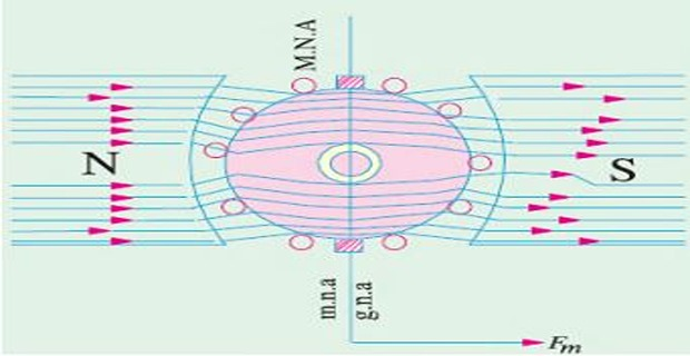
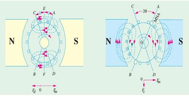
The flux is distributed symmetrically w.r.t. the polar axis
The Magnetic Neutral Axis (MNA), axis along which no emf is produced in the armature conductors because they move parallel to the line of flux.
MNA axis is \(\perp\) to the flux passing through armature
MNA also called "axis of commutation" because reversal of current in armature conductors take place across this axis
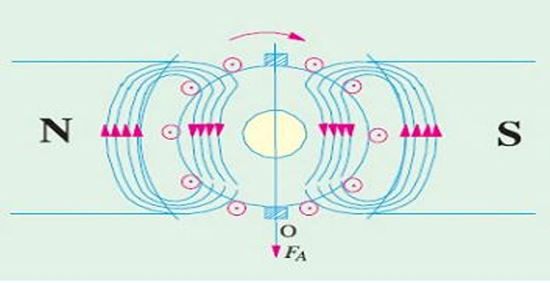
Flux set up by \(I_a\) alone field coils being unexcited
The mmf of the armature conductors combine to send flux downwards through the armature shown by vector \(OF_A\)
Under actual condition, both the mmfs (main and armature) exist simultaneously
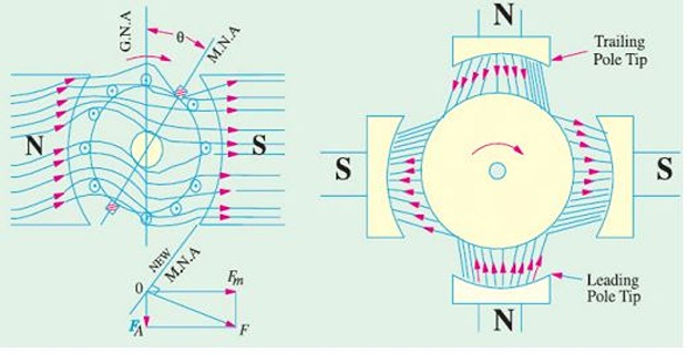
Flux through armature is no longer uniform and symmetrical rather it is distorted
Flux is crowded at the trailing pole tips but weakened or thinned out at the leading pole tips (the pole tip which is first met during rotation by armature conductors is known as leading pole tip and the other as trailing pole tip)
\(\overrightarrow{OF}=\overrightarrow{OF_{M}}+\overrightarrow{OF_{A}}\)
The new position of MNA, which is always \(\perp\) to resultant mmf \(OF\)
With the shift of MNA by \(\theta\), brush also shifts, to lie in the new position of MNA
Due to brush shift (forward lead), \(I_a\) redistribution occurs, earlier which were under the influence of \(N\)-pole comes under the influence of \(S\)-pole, and vice versa
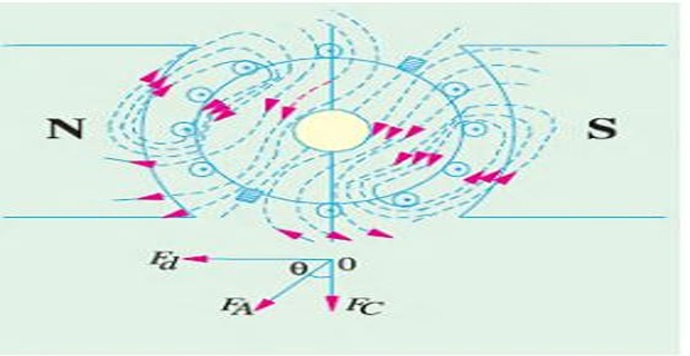
The armature mmf \(OF_A\) lie in the direction of the new position of MNA (or brush axis)
\(OF_A\) is not vertical but inclined by an angle \(\theta\)
\(OF_A\) resolved as \(OF_d\) (parallel to polar axis) and \(OF_c\) (\(\perp\) to the axis)
De-magnetizing and Cross-magnetizing
Component \(OF_c\) right angle to \(OF_m\) (representing the main mmf) produces distortion in the main field and hence called the or distorting component of the armature reaction
Component \(OF_d\) is in direct opposition of \(OF_m\) exerts a demagnetizing influence on the main pole flux called the or weakening component of the armature reaction
Cross-magnetizing conductors lie between \(\angle AOD\) and \(BOC\)
NOTE:
- For neutralizing demagnetizing effect an extra number of turns may be put on each pole\[\begin{aligned} \mbox{No. of extra turns/pole} & = \dfrac{AT_d}{I_{sh}} \cdots \mbox{for shunt generator} \\ & = \dfrac{AT_d}{I_{a}} \cdots \mbox{for series generator} \\ \end{aligned}\]
- If lead angle is given in electrical degrees, it should be converted into mechanical degrees by using\[\begin{aligned} \theta (\mbox{mechanical}) & = \dfrac{\theta (\mbox{electrical})}{\mbox{pair of poles}}\\ \theta_m & = \dfrac{\theta_e}{P/2} \end{aligned}\]
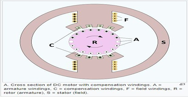
Embedded in pole shoes slots, connected in series with armature such that the current in them flows in opposite direction to that flowing in armature conductors directly below the pole shoes
Used for large dc machines subjected to large fluctuations in load, e.g. rolling mill motors and turbo-generators, etc.
To neutralize the cross-magnetizing effect of armature reaction
Absence of compensating winding result sudden shifting of flux forward and backward with every change in load
Shifting of flux will cause statically induced emf in the armature coils, whose magnitude depend upon the rapidity of change in load and the amount of change
- Compensating winding provides sufficient mmf to counterbalance the armature mmf\[\begin{aligned} Z_{c}I_{a} & =Z_{a}\left(I_{a}/A\right)\\ \Rightarrow Z_{c} & =Z_{a}/A \end{aligned}\]