Demonstrative Video
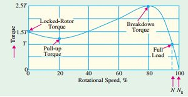
Torque/Speed Curve
\(T\) depends on \(N_r\) but the relation between two cannot be represented by a simple equation
It is easier to show the relationship in the form of a curve
\(T\): nominal full-load torque of the motor
\(T_{st}\) \((N=0)\) is 1.5\(T\) and \(T_{max}\) (also called breakdown torque) is 2.5\(T\)
Motor (Electrical) Torque: magnetic flux \(\times\) armature current
Load (Mechanical) Torque: force \(\times\) distance
Motor running in steady state, \(I_a\) is constant, Electrical torque is equal and opposite to mechanical torque
Motor is decelerating, motor torque \(<\) load torque.
Motor is accelerating, motor torque \(>\) load torque
When mechanical load increases, motor speed decreases till the motor torque becomes equal to the load torque
As long as the two torques are in balance, the motor will run at constant (not synchronous) speed
However, if the load torque exceeds 2.5\(T\), the motor will suddenly stops
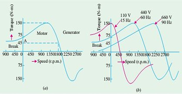
For SCIM, \(T\)/\(N\) curve depends on \(V\) and \(f\) supplied to the stator
If \(f\) is fixed, \(T\propto V^2\) and \(N_s\) depends on \(f\)
In practice, \(V\) and \(f\) are varied in the same proportion in order to maintain a constant flux in the air-gap
Shape of \(T-N\) curve remain the same but its position will shift along the X-axis
Torque of SCIM remains the same whenever slip-speed remains the same
Current-Speed Curve
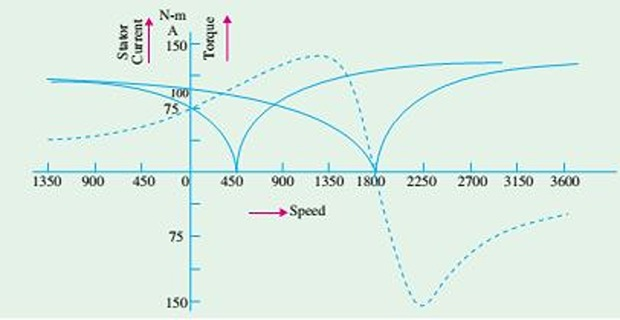
V-shaped curve having a minimum value at \(N_s\)
This minimum is equal to the magnetising current which is needed to create flux in the machine
Since \(\Phi\) is purposely kept constant, it means that magnetising current is the same at all \(N_s\)
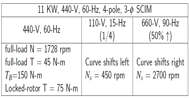
Locked rotor (for 440-V/60-Hz): Current (100 A) and Torque (75 N-m)
Variation of \(V/f\), \(I/N\) curve has the same shape, but shifts along the speed axis
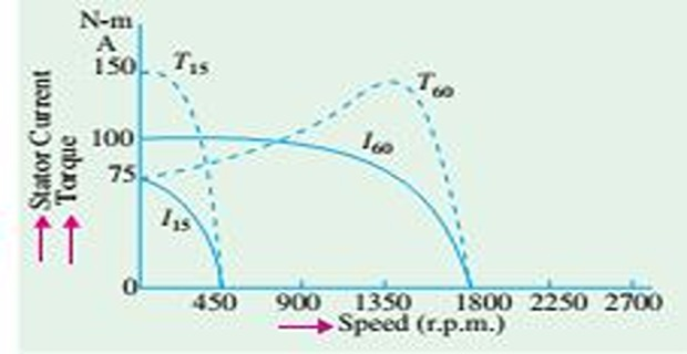
Locked rotor (for 110-V/15-Hz): Current (75 A) and Torque (150 N-m)
Conclusion:
Big advantage of frequency control method
Another advantage: it permits regenerative braking
Popularity of frequency-control IM drives is ability to develop high torque from zero to full-speed together the economy of regenerative braking
Torque-Speed Characteristics under Load
Stable operation lies over the linear portion of \(T-s\) curve
Slope of the straight line depends mainly on \(R_2\)
Higher \(R_2\) sharper the slope
- The parameters under two different load conditions are related by\[s_2 = s_1 \cdot \dfrac{T_2}{T_1} \cdot \dfrac{R_2}{R_1} \cdot \left(\dfrac{V_1}{V_2}\right)^2\]