Demonstrative Video
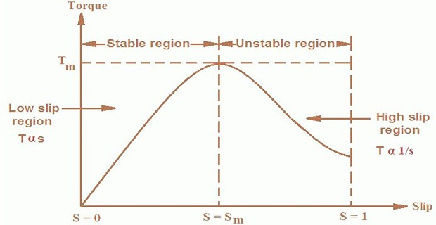
Torque-Slip Characteristics of \(3-\Phi\) IM
Three different regions are:
- low slip region
- medium slip region
- high slip region
- The torque equation is given by:\[T = \dfrac{KsE_2^2R_2}{R_2^2+(sX_2)^2}\]
At \(N_s\), \(s=0\) and therefore the torque is zero
When \(N_r \approx N_s\), \(s\) is very low and \((sX_2)^2\) is negligible as compared with \(R_2\)
- Therefore,\[T = \dfrac{K_1s}{R_2}\]
As \(R_2\) is constant, the torque becomes \(T \propto s\)
Hence, in the normal working region of the motor, the value of the slip is small and torque-slip curve is a straight line
As \(s\) increases, \(N_r\) decreases with the increase in load
The term \((sX_2)^2\) becomes large
Then, \(R_2^2\) may be neglected in comparison with \((sX_2)^2\)
- The torque becomes\[T = \dfrac{K_3R_2}{sX_2^2}\]
The torque is inversely proportional to the slip
Beyond \(T_{max}\), the value of \(T\) starts decreasing
As a result motor slows down and stops
At this stage, the overload protection must immediately disconnect the motor from the supply to prevent damage due to overheating of the motor
The motor operates from \(s=0\) and \(s=S_M\)
For a typical IM, the pull-out torque is 2 to 3 times the rated full-load torque
\(T_{st}\) is about 1.5 times the rated full load torque
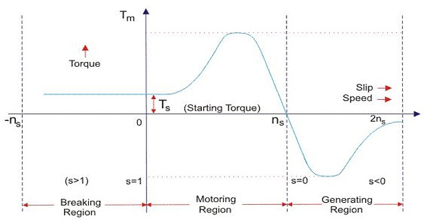
Modes of Operation of \(3-\Phi\) IM
Motor always rotates below the synchronous speed
The torque varies from zero to full load torque as the slip varies (0 to 1)
No load \(s=0\) and Standstill \(s=1\)
From curve, torque is directly proportional to the slip
The linear relationship simplifies the calculation of motor parameter to great extent
Motor runs above the synchronous speed and should be driven by a prime mover
The stator winding now the electrical energy
Torque and slip both are negative
Receives mechanical energy and delivers electrical energy
Induction generator are not used because it requires reactive power for its operation and should be supplied from outside and if it runs below synchronous speed by any means it consumes electrical energy rather than giving it at the output
The two leads or polarity of \(V\) is changed so that motor starts to rotate in the reverse direction and as a result the motor stops
This method of braking is known as and is used when motor has to stop within a very short period of time
The K.E stored in the revolving load is dissipated as heat so motor develops enormous heat energy
For this motor is disconnected from the supply before motor enters the braking mode
The other form of braking is or
If load driven by motor accelerates motor in the same direction as the motor is rotating, the speed of the motor may increase more than the synchronous speed
Motor acts as induction generator which supplies electrical energy to the mains which tends to slow down the motor to its synchronous speed and the motor stops
Effect of \(R_2\) on \(T-s\) Characteristics
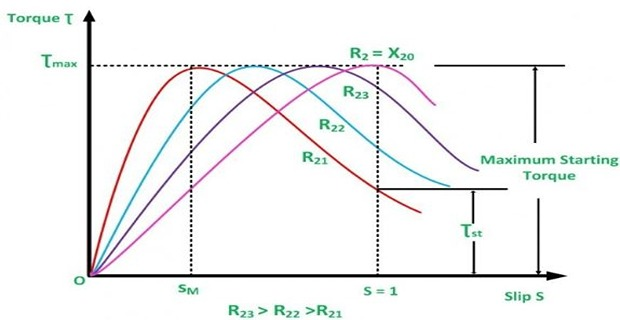
\(T_{max}\) is independent of \(R_2\)
Therefore, the effect of change in \(R_2\) is the change in \(s\) at which \(T_{max}\) takes place
Greater the \(R_2\), greater the value of \(s\) at which \(T_{max}\) occurs since \(s=R_2/X_2\)
\(T_{max}\) can be obtained at the start by adding much resistance in the rotor circuit so that \(R_2=X_2\)
When \((R_2=X_2) \Rightarrow (s= R_2/X_2 =1)\) i.e. \(T_{st} = T_{max}\)