Electrical Machines · DC Machines

DC Machine Power: Working Principle & EMF Equation

Dr. Mithun Mondal BITS Pilani, Hyderabad Campus Electrical Machines

Demonstrative Video

SECTION 01

Working Principle

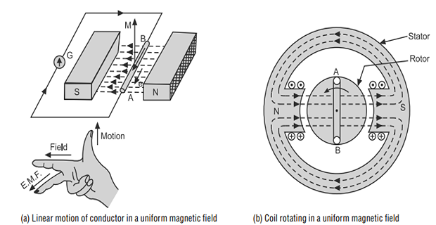
  • Basic principle of a DC generator is electro-magnetic induction i.e., when a conductor cuts across the magnetic field, an emf is induced in it.

    coil emf
    Coil Emf
SECTION 02

Generation of EMF

  • When a conductor is moved vertically upward or downward, the deflection in the galvanometer clearly shows that an emf is induced in the conductor since flux is cut by the conductor.

  • But, when it is moved horizontally (left or right), there is no deflection in the galvanometer which shows that no emf is induced in the conductor since flux cut is zero and conductor moves just parallel to the magnetic lines of force.
    Wave shape of Induced EMF
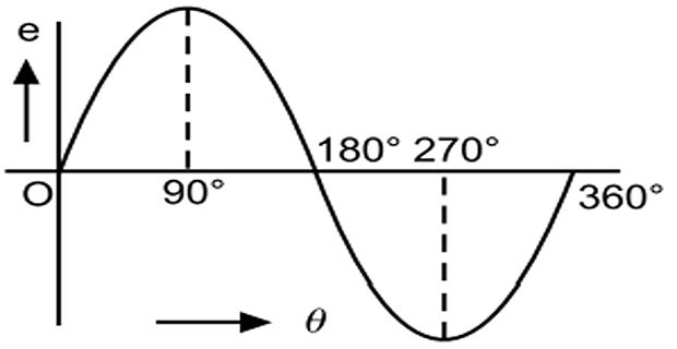
    Wave Shape Of Induced Emf
Key Concepts
  • In fact, in a generator, a coil is rotated at a constant speed of \(\omega\) radians per second in a strong magnetic field of constant magnitude.

  • An emf is induced in the coil by the phenomenon of dynamically induced emf (\(e =Blv \sin \theta; e \propto \sin \theta\)).

  • The magnitude and direction of induced emf changes periodically depending upon \(\sin\theta\).

  • Wave shape of the induced emf is AC for internal as well as external load.

  • AC is converted into DC with the help of commutator.

SECTION 03

Equation of Generated EMF

\[\begin{aligned} \Phi & =\mbox{flux/pole in weber}\\ Z & =\mbox{total number of armature conductors}\\ & =\mbox{No. of slots }\times\mbox{No. of conductors/slot}\\ P & =\mbox{No. of generated poles}\\ A & =\mbox{No. of parallel paths in armature}\\ N & =\mbox{armature rotation in rpm}\\ E & =\mbox{emf induced in any parallel path in armature}\\ E_{g} & =\mbox{generated emf in any one of the paralel paths} \end{aligned}\]
Key Concepts
\[\begin{aligned} \mbox{Average emf generated/conductor} & =d\Phi/dt~\mbox{volt}~\left(\because n=1\right)\\ \mbox{flux cut/conductor in one revolution }d\Phi & =\Phi P~\mbox{Wb}\\ \mbox{No. of revolutions/second} & =N/60\\ \Rightarrow\mbox{Time for one revolution}~dt & =60/N~\mbox{second}\\ \mbox{EMF generated/conductor} & =\dfrac{d\Phi}{dt}=\dfrac{\Phi PN}{60}~\mbox{volt}\\ \mbox{No. of parallel paths} & = A\\ \mbox{No. of conductors (in series) in one path} & = Z/2 \\ \therefore \mbox{EMF generated/path} & = \boxed{{\dfrac{\Phi PN}{60}} \times {\dfrac{Z}{A}}}\\ A & =2\cdots\cdots\mbox{wave-wound}\\ A & =P\cdots\cdots\mbox{lap-wound} \end{aligned}\]
are constants, therefore and For a given dc machine