By the end of this chapter you should be able to:
Identify the stator and rotor parts of a DC machine and say what each contributes.
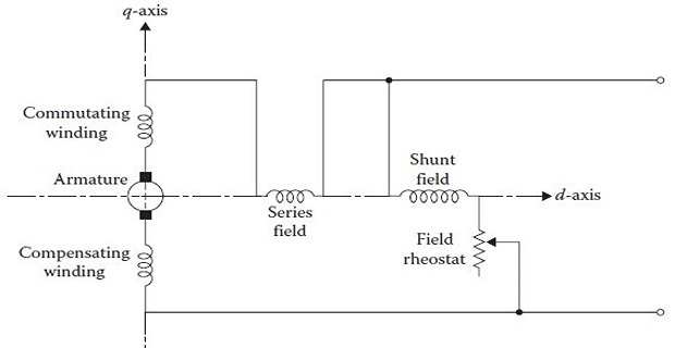
Explain the direct and quadrature axes and which windings lie on each.
State the purpose, material and reason for the material of the yoke, pole core, pole shoe and armature core.
Distinguish shunt and series field coils by their construction.
Explain why the armature core is laminated and made of silicon steel, and quantify the benefit.
Compare lap and wave windings by parallel paths and brush count.
Describe the commutator and brushes and compute volts per segment and brush area.
Size the yoke, pole and tooth cross-sections from flux and permitted flux density.
Stator and Rotor
A DC machine has two basic parts: the stator, which stands still, and the rotor, which rotates.
The stator has salient poles that are excited by one or more field windings.
The armature winding is located on the rotor, with current flowing through it by carbon brushes making contact with copper commutator segments.
Both the main poles and the armature core are made of laminated materials to reduce core losses.
Big DC machines also have commutating poles between the main poles of the stator.
Each commutating pole has its own winding, known as the commutating winding — interpoles or compoles.

The Direct and Quadrature Axes
The field windings are located around the pole cores and are connected in series and/or in shunt — that is, in parallel — with the armature circuit.
The shunt winding is made up of many turns of relatively thin wire, whereas the series winding has only a few turns and is made up of thicker wire.
The series and shunt windings are located on the d-axis — called the field axis, or direct axis — because the air-gap flux distribution due to the field windings is symmetric about the centre line of the field poles.
The compensating and commutating windings, and the brushes, are located on the q-axis — the quadrature axis — because it is 90 electrical degrees from the d-axis and represents the neutral zone.
It carries a small current — a few percent of the load, as Chapter 20 showed — across the full terminal voltage. To produce the required ampere-turns from a small current it needs many turns, and to fit them in it uses fine wire.
Its resistance is high, typically tens or hundreds of ohms.
It carries the full armature or load current, so the wire must be heavy. Since the current is already large, only a few turns are needed for the same ampere-turns.
Its resistance is very low, a fraction of an ohm, because it is in the main current path where any resistance is a loss.
A coil being switched by the commutator is momentarily short-circuited by a brush. If it were generating an EMF at that instant, a large circulating current would flow and the brush would spark badly.
The brushes are therefore placed on the q-axis, midway between the poles, where the flux density is zero and so is the coil EMF. Armature reaction shifts that neutral zone under load, which is precisely the problem Chapters 30 and 31 solve — with the interpoles and compensating windings that also sit on the q-axis.
Cut-Out Model
The complete assembly of the various parts of a DC machine, shown in scattered form, together with the essential parts.

Magnetic Frame or Yoke
The outer cylindrical frame to which the main poles and interpoles are fixed is called the yoke. It also helps to fix the machine on its foundation.
It provides mechanical protection to the inner parts of the machine.
It provides a low-reluctance path for the magnetic flux.
Smaller machines: cast iron.
Larger machines: cast steel or fabricated rolled steel, since these materials have better magnetic properties as compared to cast iron.
Flux leaving a north pole enters the yoke and divides, half going each way round to the adjacent south poles. The yoke cross-section therefore carries
where \(\Phi_p\) is the total pole flux — the useful air-gap flux \(\Phi\) multiplied by the leakage coefficient of Chapter 4.
The yoke is not laminated, and does not need to be. It carries a steady flux in a normally excited machine, so there is no alternating flux to drive eddy currents. Only the parts that see a changing flux need laminating — which is why the yoke may be a solid casting while the armature core never can be.
Problem. A 4-pole DC machine has a useful flux of 30 mWb per pole and a leakage coefficient of 1.15. The permitted flux density is 1.4 T in the pole core and 1.2 T in the yoke. Find the required cross-sectional areas.
Total pole flux. The pole core must carry the useful flux plus the leakage:
Pole core area.
Yoke flux and area. The flux divides two ways in the yoke:
Comment. The yoke needs only about 58 % of the pole-core area, despite being made of a poorer magnetic material — because it carries only half the flux. Note that the leakage coefficient is applied to the pole and yoke but not to the air gap: leakage flux never crosses the gap and does no useful work, but the iron must still carry it, which is exactly why Chapter 4 insisted on the distinction.
Pole Core and Pole Shoes
These are fixed to the magnetic frame or yoke by bolts, and serve the following purposes:
Support the field or exciting coils.
Spread out the magnetic flux over the armature periphery more uniformly.
Since pole shoes have a larger cross-section, the reluctance of the magnetic path is reduced.
They are usually made of thin cast steel or wrought iron laminations, which are riveted together under hydraulic pressure.

Field or Exciting Coils
Enamelled copper wire is used for the construction.
The coils are wound on a former and then placed around the pole core.
When DC is passed through the field winding, it magnetises the poles, which produce the required flux.
The field coils of all the poles are connected in series in such a way that when current flows through them, adjacent poles attain opposite polarity.
The last point is not a detail but a requirement of the magnetic circuit. Flux must leave a north pole, cross the gap into the armature, travel through the armature core, and return across the gap into a south pole. If two adjacent poles were both north, the flux would have nowhere to return and the magnetic circuit would not close.
A common fault after rewinding is one coil connected backwards, giving two adjacent like poles. The machine then generates far below its rated voltage, and the fault is found by passing a small DC current through the field and testing each pole face with a compass or a piece of steel.
Armature Core
The armature core is cylindrical in shape and keyed to the rotating shaft. At the outer periphery, slots are cut which accommodate the armature winding.
It houses the conductors in the slots.
It provides an easy path for magnetic flux.
Silicon steel — against hysteresis loss.
Lamination — against eddy-current loss.
The two losses have different causes and need different remedies.

Since the armature is the rotating part of the machine, reversal of flux takes place in the core, hence hysteresis losses are produced.
To minimise these losses, silicon steel material is used for its construction.
This is Chapter 6's Steinmetz law in practice: adding a few percent of silicon narrows the hysteresis loop and so reduces the loss per cycle.
When the core rotates, it cuts the magnetic field and an EMF is induced in it.
This EMF circulates eddy currents, which result in eddy-current loss.
To reduce these losses the armature core is laminated — in other words, about 0.3 to 0.5 mm thick stampings are used for its construction.
Each lamination or stamping is insulated from the other by a varnish layer.
Chapter 7 established that eddy-current loss varies as the square of the lamination thickness, \(P_e \propto t^{2}\). That square law is what makes lamination so extraordinarily effective, as Example 22.2 shows.
Problem. An armature core has a net iron length of 250 mm, built from 0.5 mm stampings with a stacking factor of 0.90. Find the gross core length and the number of laminations. By what factor does lamination reduce the eddy-current loss compared with a solid core of the same gross length?
Gross length. The varnish insulation means the stack is longer than the iron it contains:
Number of laminations.
Eddy-loss reduction. Since \(P_e \propto t^{2}\), comparing a solid core of thickness 277.8 mm with laminations of 0.5 mm:
Comment. Lamination cuts the eddy-current loss by a factor of about three hundred thousand. Nothing else in machine design offers a return remotely like it, which is why every core carrying alternating flux — in this book and in industry — is laminated without exception.
The stacking factor is the price. Ten percent of the axial length is varnish and air rather than iron, so the core must be built 11 % longer than the magnetic calculation alone would suggest. Thinner laminations reduce eddy loss further but worsen the stacking factor and cost more to punch and assemble — which is why 0.35 to 0.5 mm is the usual compromise.
Armature Winding, Lap and Wave
The insulated conductors housed in the armature slots, suitably connected, are known as the armature winding.
The armature winding acts as the heart of a DC machine. It is the place where one form of power is converted to the other: in a generator, mechanical power is converted into electrical power; in a motor, electrical power is converted into mechanical power.
On the basis of connections there are two types of armature winding — lap winding and wave winding.
Connections are such that the number of parallel paths is equal to the number of poles.
If the machine has \(P\) poles and \(Z\) armature conductors, there will be \(P\) parallel paths, each path having \(Z/P\) conductors in series.
The number of brushes is equal to the number of parallel paths, of which half are positive and the remaining half negative.
Connections are such that the number of parallel paths is only two, irrespective of the number of poles.
If the machine has \(Z\) armature conductors, there will be only two parallel paths, each having \(Z/2\) conductors in series.
The number of brushes is two — again, equal to the number of parallel paths.
| Feature | Lap | Wave |
|---|---|---|
| Parallel paths \(A\) | \(P\) | 2 |
| Conductors in series per path | \(Z/P\) | \(Z/2\) |
| Number of brush sets | \(P\) | 2 |
| Generated EMF | Lower | Higher (by \(P/2\)) |
| Current capability | Higher | Lower |
| Suited to | Low voltage, high current | High voltage, low current |
| Equalisers needed? | Yes | Not normally |
Note the consistency with Chapter 21: \(Z/P\) for lap and \(Z/2\) for wave are both instances of the general rule \(Z/A\), with \(A = P\) and \(A = 2\) respectively.
Commutator
The commutator is an important part of a DC machine and serves the following purposes:
It connects the rotating armature conductors to the stationary external circuit through the brushes.
It converts the AC induced in the armature conductors into unidirectional current in the external load circuit in generator action; whereas in motor action it converts the alternating torque produced in the armature into unidirectional, continuous torque.
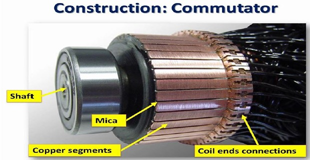
The commutator is of cylindrical shape and is made up of wedge-shaped hard-drawn copper segments.
The segments are insulated from each other by a thin sheet of mica.
The segments are held together by means of two V-shaped rings that fit into V-grooves cut into the segments.
Each armature coil is connected to a commutator segment through a riser.
Adjacent segments are joined by one coil, so the voltage between them is the EMF of that coil. For a lap winding with \(C\) coils and \(C\) segments,
Design practice keeps the average below about 15 V, because a higher value risks flashover across the mica and, in the worst case, a ring fire that arcs right round the commutator.
Problem. A 4-pole lap-wound machine has 48 slots with 2 coils per slot and generates 250 V. Find the number of commutator segments and the average voltage between adjacent segments. What would it be if the same armature were wave-wound?
Segments. One segment per coil:
Lap winding. With \(A = P = 4\), each path contains \(96/4 = 24\) coils and develops 250 V, so
Wave winding. The same armature wave-wound generates \(P/2 = 2\) times the EMF, so \(E = 500\) V, and each of the 2 paths contains \(96/2 = 48\) coils:
Comment. The two are identical — and that is not a coincidence. The voltage between adjacent segments is simply the EMF generated in one coil, and one coil generates the same EMF whatever it is connected to. The winding decides how coils are grouped into paths, not what each coil produces.
At 10.4 V both are comfortably below the 15 V guideline. Raising the machine's voltage without adding coils would push this up, and this is the real ceiling on DC machine voltage: not insulation to earth, but flashover between neighbouring segments a millimetre apart. It is why DC machines above about 1500 V are rare, while AC machines run at tens of kilovolts.
Brushes and Brush Rocker
Brushes are pressed upon the commutator and form the connecting link between the armature winding and the external circuit.
They are usually made of high-grade carbon, because carbon is a conducting material and at the same time, in powdered form, provides a lubricating effect on the commutator surface.
Brushes are held in position around the commutator by brush holders and the rocker.
It holds the spindles of the brush holders.
It is fitted onto the stationary frame of the machine with nuts and bolts.
By adjusting its position, the position of the brushes over the commutator can be adjusted to minimise sparking at the brushes.
Carbon is a far worse conductor than copper, and a carbon brush drops about 1 V at its contact — 2 V for the pair, a loss of 800 W in a 400 A machine. A copper brush would drop almost nothing. So why is carbon universal?
It lubricates. Carbon powder forms a film on the commutator that lets the brush slide with little friction and little wear on the copper.
It is sacrificial. A brush costs a few rupees and takes minutes to replace; a commutator is machined into the armature and costs a fortune. The soft component is deliberately the cheap one.
Its resistance helps commutation. The contact resistance limits the circulating current in a coil being short-circuited by the brush — the very effect Chapter 31 relies on to control sparking.
The brush drop is not a design failure but a design choice, accepted because the alternative is worse.
Problem. A 4-pole lap-wound machine carries an armature current of 400 A. The permitted brush current density is 0.09 A/mm² and each brush measures 25 mm × 32 mm. Find the number of brushes per arm and the total brush contact loss, taking 1 V drop per brush.
Current per brush arm. A lap winding needs \(P = 4\) brush arms, sharing the armature current equally:
Contact area required.
Brushes per arm. Each brush offers \((25)(32) = 800\) mm²:
Eight brushes in all, giving an actual density of \(100/1600 = 0.0625\) A/mm² — comfortably inside the limit.
Contact loss. The current passes through one brush entering the commutator and another leaving it, so the total drop is 2 V:
Comment. The brush loss must always be rounded up to a whole number of brushes, never down — and in practice designers use several small brushes per arm rather than one large one, because small brushes follow an imperfectly round commutator better and a single failure loses less of the contact area.
Note that the brush loss depends on current alone, not on voltage. In a 250 V machine 800 W is 0.8 % of the output; in a 24 V machine of the same current it would be 8 %. This is why low-voltage DC machines are relatively inefficient, and why brush drop matters most in exactly the high-current applications that lap windings serve.
Housings, Bearings and Shaft
Attached to the ends of the main frame and support the bearings. The front housing supports the bearing and the brush assemblies, whereas the rear housing usually supports the bearing only.
May be ball or roller bearings, fitted in the end housings. Their function is to reduce friction between the rotating and stationary parts of the machine. Mostly high-carbon steel is used, as it is a very hard material.
Made of mild steel with maximum breaking strength. Used to transfer mechanical power from or to the machine. The rotating parts — armature core, commutator, cooling fan and so on — are keyed to the shaft.
These parts carry no flux and no current, but they set the air gap, and the air gap dominates the machine's reluctance as Chapter 4 showed. Bearing wear that lets the rotor sag by a few tenths of a millimetre changes the gap, unbalances the magnetic pull, and produces both vibration and a measurable drop in flux. Mechanical precision here is a magnetic requirement, not merely a mechanical one.
Problem. A 4-pole machine has an armature diameter of 350 mm and core length 250 mm, with 48 slots each 12 mm wide and a stacking factor of 0.90. The ratio of pole arc to pole pitch is 0.70 and the useful flux is 30 mWb per pole. Find the flux density in the air gap and in the armature teeth.
Pole pitch and pole arc.
Air-gap flux density.
Tooth dimensions.
Teeth under one pole arc.
Tooth flux density. The same flux now passes through iron only, allowing for the stacking factor:
Comment. The tooth density is \(1.455/0.624 = 2.33\) times the gap density, because the flux that crossed the whole pole arc must now squeeze through the teeth alone — the slots carry none of it, and 10 % of what remains is varnish.
This is why the teeth are the first part of a DC machine to saturate. At 1.46 T they are already past the knee of the B-H curve from Chapter 5, while the gap sits at a modest 0.62 T and the yoke at around 1.2 T. Any attempt to raise the machine's flux runs into the teeth long before it troubles anything else — and that, not the gap, is what sets the practical limit on the flux per pole.
Materials Summary
| Part | Material | Why | Laminated? |
|---|---|---|---|
| Yoke, small machines | Cast iron | Cheap, easily cast | No |
| Yoke, large machines | Cast steel or rolled steel | Better magnetic properties than cast iron | No |
| Pole core and shoe | Thin cast steel or wrought iron laminations | Carries flux; riveted under hydraulic pressure | Yes |
| Field coils | Enamelled copper wire | Conducts; enamel insulates in minimum space | — |
| Armature core | Silicon steel, 0.3–0.5 mm stampings | Silicon cuts hysteresis; lamination cuts eddy loss | Yes |
| Lamination insulation | Varnish layer | Blocks eddy current between stampings | — |
| Armature winding | Insulated copper | Seat of the energy conversion | — |
| Commutator segments | Hard-drawn copper | Conducts and resists brush wear | — |
| Segment insulation | Mica | Insulates; wears at a rate matching copper | — |
| Brushes | High-grade carbon | Conducts, lubricates, sacrificial, aids commutation | — |
| Bearings | High-carbon steel | Very hard | — |
| Shaft | Mild steel | Maximum breaking strength | — |
Summary and Key Formulas
A DC machine has a stator with salient poles and field windings, and a rotor carrying the armature winding, commutator and brushes. Large machines add interpoles.
Field windings lie on the d-axis; brushes, interpoles and compensating windings on the q-axis, the neutral zone 90 electrical degrees away.
The shunt winding has many turns of thin wire; the series winding few turns of thick wire.
The yoke gives mechanical protection and a low-reluctance flux path — cast iron for small machines, cast or rolled steel for large. It carries half the pole flux.
Pole cores and shoes support the field coils, spread the flux uniformly and reduce reluctance by their larger cross-section.
Field coils are of enamelled copper, connected so that adjacent poles have opposite polarity.
The armature core uses silicon steel against hysteresis and 0.3–0.5 mm varnish-insulated laminations against eddy currents.
Lap gives \(A = P\) paths, \(Z/P\) conductors per path and \(P\) brush sets; wave gives \(A = 2\), \(Z/2\) and 2 brush sets.
The commutator is hard-drawn copper segments insulated by mica, held by V-rings, each coil connected through a riser.
Carbon brushes conduct, lubricate, are sacrificial, and their contact resistance aids commutation — at the cost of about 1 V drop each.
| Quantity | Formula | Notes |
|---|---|---|
| Pole flux | \(\Phi_p = C_l\Phi\) | \(C_l\) = leakage coefficient |
| Pole core area | \(A_p = \Phi_p/B_p\) | — |
| Yoke flux | \(\Phi_y = \Phi_p/2\) | flux divides two ways |
| Yoke area | \(A_y = \Phi_p/2B_y\) | — |
| Gross core length | \(L_{\text{gross}} = L_{\text{net}}/k_s\) | \(k_s\) = stacking factor |
| Number of laminations | \(n = L_{\text{gross}}/t\) | \(t\) = 0.3–0.5 mm |
| Eddy-loss reduction | \(\left(t_{\text{solid}}/t_{\text{lam}}\right)^{2}\) | since \(P_e \propto t^{2}\) |
| Pole pitch | \(\tau = \pi D/P\) | — |
| Slot pitch | \(\pi D/S\) | — |
| Air-gap flux density | \(B_g = \Phi/(\text{pole arc} \times L)\) | — |
| Tooth flux density | \(B_t = \Phi/(n_tw_tLk_s)\) | saturates first |
| Volts per segment | \(EP/C\) lap, \(2E/C\) wave | keep below ~15 V |
| Brush contact area | \(A_b = I_{\text{arm}}/J\) | \(I_{\text{arm}} = I_a/P\) for lap |
| Brush contact loss | \(P_b = 2V_bI_a\) | about 1 V per brush |
Common Mistakes
Sizing the yoke for the full pole flux. It carries only half, because the flux divides both ways round.
Forgetting the leakage coefficient on the pole and yoke. The iron carries the leakage flux even though the air gap does not.
Assuming the yoke must be laminated. It carries a steady flux, so it need not be — and usually is not.
Omitting the stacking factor. About 10 % of the axial length is varnish, so the gross length exceeds the net iron length.
Computing tooth density over the whole core area. The slots carry no flux; only the tooth iron does.
Swapping the shunt and series winding descriptions. Shunt is many thin turns; series is few thick turns.
Putting the brushes on the d-axis. They belong on the q-axis, the neutral zone, where the coil EMF is zero.
Connecting all field coils to give the same polarity. Adjacent poles must alternate or the magnetic circuit cannot close.
Expecting lap and wave to give different volts per segment. They do not — one coil generates the same EMF either way.
Treating the brush drop as proportional to voltage. It is a roughly constant 1 V per brush regardless of the machine's voltage, so it hurts low-voltage machines most.
Chapter Review
For sizing problems, decide first whether the part carries the full pole flux or half of it, and whether the leakage coefficient applies.
P22.1 A 6-pole machine has 40 mWb useful flux per pole and a leakage coefficient of 1.2. Find the yoke area for a yoke flux density of 1.1 T.
Show answer
\[\Phi_p = (1.2)(40) = 48~\mathrm{mWb}, \qquad \Phi_y = \frac{48}{2} = 24~\mathrm{mWb}\]\[A_y = \frac{24\times10^{-3}}{1.1} = 21.82\times10^{-3}~\mathrm{m^{2}} = 218.2~\mathrm{cm^{2}}\]P22.2 An armature core has a gross length of 300 mm built from 0.35 mm stampings. Find the number of laminations and the net iron length for a stacking factor of 0.92.
Show answer
\[n = \frac{300}{0.35} = 857~\text{laminations}\]\[L_{\text{net}} = (0.92)(300) = 276~\mathrm{mm}\]P22.3 By what factor does changing from 0.5 mm to 0.35 mm laminations reduce the eddy-current loss?
Show answer
The loss falls to 49 %, a reduction of 51 %. The penalty is more stampings to punch and assemble, and a slightly worse stacking factor.\[\frac{P_{e,0.35}}{P_{e,0.50}} = \left(\frac{0.35}{0.50}\right)^{2} = (0.70)^{2} = 0.49\]P22.4 A 6-pole lap-wound machine has 72 coils and generates 220 V. Find the average volts between adjacent commutator segments.
Show answer
This exceeds the 15 V guideline. The remedy is more coils — 96 coils would give \((220)(6)/96 = 13.75\) V, safely inside the limit.\[V_{\text{seg}} = \frac{EP}{C} = \frac{(220)(6)}{72} = 18.33~\mathrm{V}\]P22.5 A 4-pole lap machine carries 250 A. With a brush current density of 0.08 A/mm², find the contact area needed per brush arm.
Show answer
\[I_{\text{arm}} = \frac{250}{4} = 62.5~\mathrm{A}, \qquad A_{\text{req}} = \frac{62.5}{0.08} = 781~\mathrm{mm^{2}}\]P22.6 For the machine of P22.5, find the brush contact loss and express it as a percentage of output if the terminal voltage is (a) 500 V and (b) 50 V.
Show answer
\[P_b = (2)(250) = 500~\mathrm{W}\]Ten times worse at the lower voltage, since the loss depends on current alone.\[\text{(a) } \frac{500}{(500)(250)} = 0.40\,\%, \qquad \text{(b) } \frac{500}{(50)(250)} = 4.0\,\%\]P22.7 A machine has an armature diameter of 300 mm, 36 slots of width 10 mm and a stacking factor of 0.90. Find the slot pitch and the tooth width.
Show answer
\[\text{slot pitch} = \frac{\pi(0.300)}{36} = 26.18~\mathrm{mm}\]\[\text{tooth width} = 26.18 - 10 = 16.18~\mathrm{mm}\]P22.8 Explain why the armature core must be laminated but the yoke need not be.
Show answer
Eddy currents are induced only by a changing flux. As the armature rotates, each part of its iron passes alternately under north and south poles, so the flux in it reverses at a frequency \(f = PN/120\) — hence eddy currents, and hence lamination.The yoke, being stationary and carrying flux from a steadily excited field, sees an essentially constant flux. With no rate of change there is no induced EMF and no eddy current, so the yoke may be a solid casting — which is also stronger and cheaper.
The pole is an intermediate case: its main flux is steady, but the armature slots sweeping past its face cause a small ripple, so it is laminated as a precaution against local face heating.
P22.9 Why are the brushes placed on the quadrature axis, and what happens under load?
Show answer
A coil passing under a brush is momentarily short-circuited by it. The q-axis is the magnetic neutral zone, midway between poles, where the flux density and therefore the coil EMF are zero — so no large current circulates in the shorted coil and the brush does not spark.Under load the armature current produces its own mmf, which distorts the main field and shifts the neutral zone away from the geometric q-axis. The brushes are then no longer at the true neutral, the shorted coil does generate an EMF, and sparking begins.
This is armature reaction (Chapter 30), and the remedies — shifting the brush rocker, adding interpoles, adding a compensating winding — occupy Chapter 31.
P22.10 A designer wants to raise a DC machine's terminal voltage from 250 V to 750 V without changing the armature. What is the obstacle?
Show answer
The volts between adjacent commutator segments would triple. If the machine were at the typical 10 V per segment it would rise to 30 V, well beyond the ~15 V guideline, risking flashover across the mica and possibly a ring fire around the commutator.The remedies are to increase the number of coils and segments proportionally, which needs a larger commutator and more slots, or to accept a physically bigger machine. This segment-voltage limit — not insulation to earth — is the reason DC machines are rarely built above about 1500 V, while AC machines with no commutator run at tens of kilovolts.
MCQ 1. The yoke of a large DC machine is usually made of:
(a) cast iron (b) cast steel or rolled steel (c) silicon steel laminations (d) aluminiumShow answer
(b) cast steel or rolled steel, which has better magnetic properties than cast iron. Cast iron is used for smaller machines.MCQ 2. The yoke carries a flux equal to:
(a) the full pole flux (b) half the pole flux (c) twice the pole flux (d) the air-gap fluxShow answer
(b) half the pole flux, since it divides both ways round to the adjacent poles.MCQ 3. The armature core is made of silicon steel principally to reduce:
(a) eddy-current loss (b) hysteresis loss (c) copper loss (d) friction lossShow answer
(b) hysteresis loss. Lamination is what reduces eddy-current loss.MCQ 4. Armature laminations are typically:
(a) 0.03–0.05 mm (b) 0.3–0.5 mm (c) 3–5 mm (d) 30–50 mmShow answer
(b) 0.3–0.5 mm, insulated from one another by a varnish layer.MCQ 5. In a lap winding the number of brush sets equals:
(a) 2 (b) \(P\) (c) \(P/2\) (d) \(Z\)Show answer
(b) \(P\) — equal to the number of parallel paths, half positive and half negative.MCQ 6. Commutator segments are insulated from one another by:
(a) varnish (b) mica (c) paper (d) airShow answer
(b) mica, chosen partly because it wears at a rate comparable to the copper.MCQ 7. Brushes are made of carbon chiefly because carbon:
(a) is the best conductor (b) conducts and also lubricates (c) is magnetic (d) never wearsShow answer
(b) conducts and also lubricates in powdered form. It is also sacrificial and its resistance aids commutation.MCQ 8. The brushes of a DC machine are located on the:
(a) d-axis (b) q-axis (c) pole centre (d) yokeShow answer
(b) q-axis — the neutral zone, 90 electrical degrees from the field axis.MCQ 9. Which part of the magnetic circuit normally saturates first?
(a) the yoke (b) the air gap (c) the armature teeth (d) the pole shoeShow answer
(c) the armature teeth, because the flux that crossed the whole pole arc must pass through the tooth iron alone.MCQ 10. The function of the brush rocker is to:
(a) support the bearings (b) hold the brush-holder spindles and allow brush position adjustment (c) carry the flux (d) cool the commutatorShow answer
(b) hold the brush-holder spindles and allow the brush position to be adjusted to minimise sparking.
Name the stator and rotor parts of a DC machine and state the function of each.
Explain the direct and quadrature axes, say which windings lie on each, and why.
State the purposes of the yoke and justify the choice of material for small and large machines.
Explain why pole shoes are used, and give three reasons.
Contrast the construction of shunt and series field windings, and explain the reason for the difference.
Explain why the armature core needs both silicon steel and lamination, identifying which loss each addresses.
Describe the construction of a commutator and explain the choice of hard-drawn copper and mica.
Give four reasons why brushes are made of carbon despite its poor conductivity.
The machine has been taken apart. Chapter 23 concentrates on the one component whose function still needs proper explanation — the commutator. Its construction is now familiar; what remains is the process of commutation itself, coil by coil, and why it limits the machine's speed and current.
Chapters 24 and 25 develop the armature windings whose parallel-path counts were quoted in Section 22-8 — the coil pitches, the winding tables, why lap windings need equaliser rings and wave windings do not, and how to choose between them.
The quadrature axis introduced in Section 22-2 returns in Chapter 30, when armature reaction shifts the neutral zone away from it under load, and in Chapter 31, when the interpoles and compensating windings mentioned in Section 22-1 are finally put to work.