Demonstrative Video
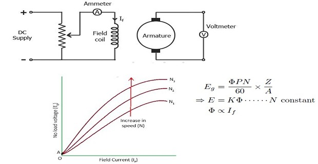
Magnetic or Open-circuit Characteristic (O.C.C)
Relation between \(E_0\) and \(I_f\) at a given fixed speed
Magnetization curve for the material of the electromagnets
Shape is practically the same for all generators
Internal Characteristics \(\left(E/I_a\right)\)
Relation between \(E\) actually induces in the armature (after demagnetization effect) and \(I_a\)
Characteristics is of mainly interest to the designer
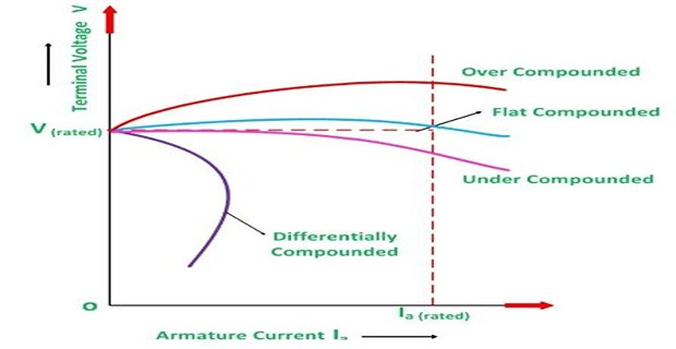
External Characteristics \(\left(V/I\right)\)
Performance characteristics or voltage-regulating curve
Relation between load \(V\) and \(I\)
great importance in judging the suitability of a generator for a practical purpose
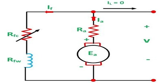
No-load Characteristics
No armature reaction generated voltage is straight line
Voltage drop \(\Delta V_{AR}\) because of armature reaction
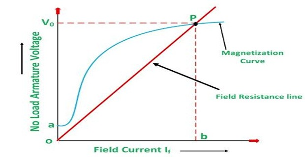
Operating Point \(P\), intersection between generator external and load characteristics by the relation \(V_L=I_LR_L\)
\(P\) gives operating value of terminal \(V\) and \(I\)

 |
|
This voltage causes \(I_f=V/R_f\) to flow in the field winding
The flux is increased by mmf produced by \(I_f\)
As a result \(E_g\) increases, which further increase \(V\)
 |
|
If \(\Phi_{res} = 0\) disconnect the field and apply a DC voltage to the field winding.This process is called Flashing the field.
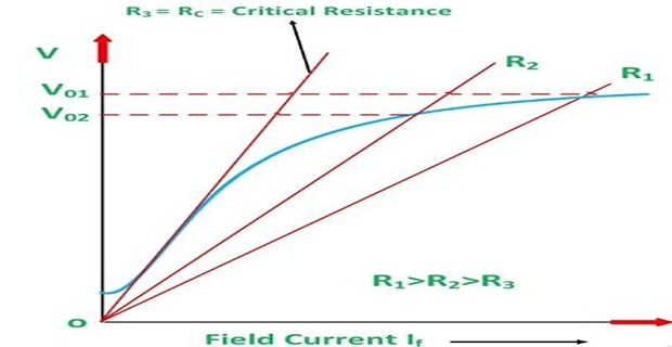
A decrease in \(R_f\) reduces the slope of \(R_f\) line resulting in a higher voltage, and vice-versa
If \(R_f\) is increased to \(R_c\), the \(R_f\) line becomes tangent to the initial part of the magnetization curve
If \(R_f\) is higher than \(R_c\), the generator fails to excite.
At \(N_c\) the \(R_f\) line becomes tangential to the magnetization curve.
Below \(N_c\) the voltage will not build up.


 |
|
If \(N_{se}\) is lesser than required to be flat compounded, then the generator is called to be under compounded.
In Differential Compounded \(V_T \Downarrow\Downarrow\) with \(I_a \Uparrow\).