SINGLE PHASE TRANSFORMER
OBJECTIVE
To determine the parameters of the equivalent circuit of a single phase transformer and predetermine the performance characteristics, by performing the OC and SC test on single phase transformer
|
NAME PLATE DETAILS OF SINGLE PHASE TRANSFORMER |
|
|
KVA Rating |
2 KVA |
|
HV Volts |
230 VAC |
|
LV Volts |
115 VAC |
|
HV current |
8.6 A |
|
LV current |
17.3 A |
|
Winding type |
Core |
APPARATUS REQUIRED:
|
S.No. |
Name of the Equipment |
Range |
Quantity |
Type |
|
1. |
Single Phase Verica |
0 to 230V/15 A
|
1 No
|
Core |
|
2. |
Voltmeter |
0 to 150 V |
1 No |
Digital |
|
3. |
Voltmeter |
0 to 50 V |
1 No |
Digital |
|
4. |
Ammeter |
5 A |
1 No |
Digital |
|
5. |
Ammeter |
10 A |
1 No |
Digital |
|
6. |
Wattmeter ( LPF ) |
150/300V/10A |
1 No |
Digital |
|
7. |
Wattmeter ( UPF ) |
75/150/20A |
1 No |
Digital |
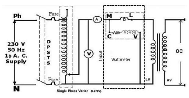
CIRCUIT DIAGRAM FOR OPEN CIRCUIT TEST:
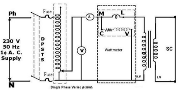
CIRCUIT DIAGRAM FOR SHORT CIRCUIT TEST:
INTRODUCTION:
A transformer is a static device comprising of two coils coupled through a magnetic medium connecting two ports at different (sometime same) voltage levels in an electric system allowing the interchange of electrical energy in either direction via magnetic field. The schematic diagram of a transformer is shown in Figure.
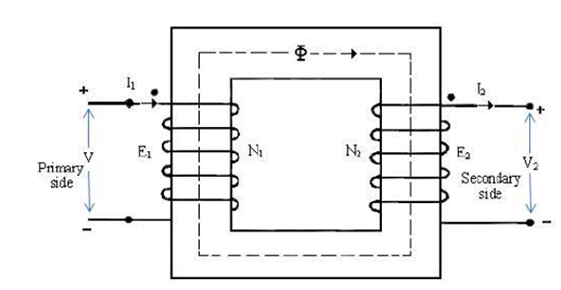
An ideal transformer obeys the following relations:
Impedance seen on primary (impedance-transformation property)
THEORY:
- Transformer is a device that transfers electrical energy from one circuit to another by electromagnetic induction (transformer action).
- The electrical energy is always transferred without a change in frequency, but may involve changes in magnitudes of voltage and current.
- Because a transformer works on the principle of electromagnetic induction, it must be used with an input source voltage that varies in amplitude.
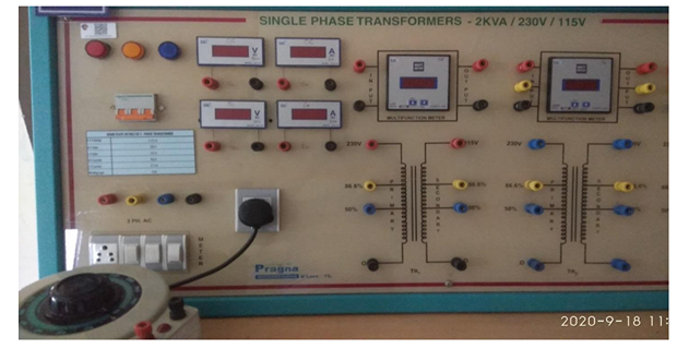
EM LAB SET-UP:
CONNECTION FOR O.C TEST:
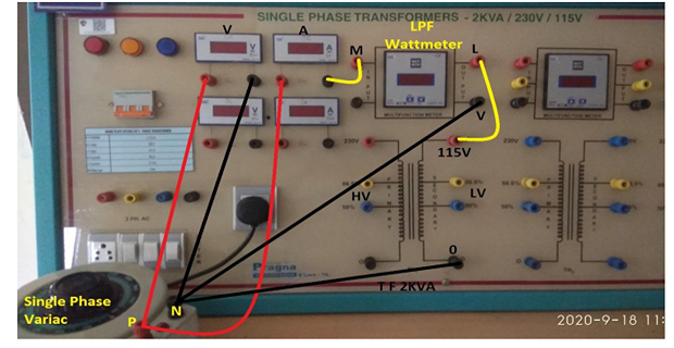
- Single Phase Verica Positive (R) to Ammeter (R)
- Single Phase Verica (R) to Voltmeter (R)
- Ammeter (B) to Wattmeter M (LPF)
- Wattmeter L to LV Side T/F 115V(R)
- Single Phase Verica Negative (B) to Voltmeter (B)
- Single Phase Verica Negative (B) to Wattmeter V
- Single Phase Verica Negative (B) to LV Side T/F 0 (B)
- HV Side is Open
PROCEDURE FOR O.C TEST:
- Connect the circuit for no-load test as per the circuit diagram.
- Keep the variac in minimum position and switch ON the 1-ɸ AC supply.
- Apply the rated voltage to the LV side of the transformer by properly adjusting the variac.
- Note down the readings of various meters such as Ammeter, Voltmeter & Wattmeter.
- After taking the readings, put the variac to minimum position & Switch OFF the 1-ɸ AC supply
OBSERVATION TABLE FOR O.C TEST:
|
S.No. |
Voc(V) |
Ioc(A)
|
Woc= W× M.F.(w)
|
|
|
|
|
|
CONNECTION FOR S.C TEST:
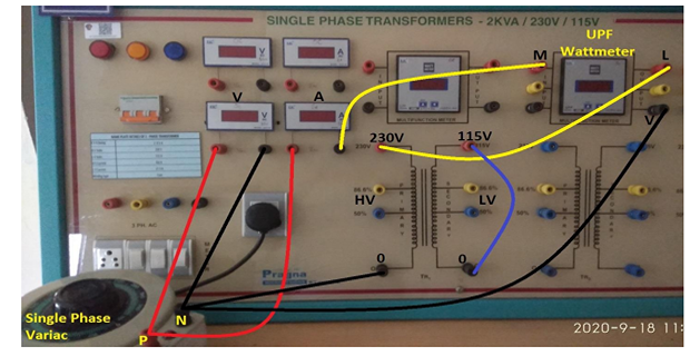
- Single Phase Verica Positive (R) to Ammeter (R)
- Single Phase Verica (R) to Voltmeter (R)
- Ammeter (B) to Wattmeter M (UPF)
- Wattmeter L to HV Side T/F 230V(R)
- Single Phase Verica Negative (B) to Voltmeter (B)
- Single Phase Verica Negative (B) to Wattmeter V
- Single Phase Verica Negative (B) to HV Side T/F 0 (B)
- LV Side is Short
PROCEDURE FOR S.C TEST:
- Connect the circuit for SC test as per the circuit diagram, with appropriate range of meters.
- Keep the variac in minimum position and switch ON the 1-ɸ AC supply.
- Apply appropriate voltage (low voltage) to the transformer by adjusting the variac such that rated current flows through the transformer.
- Note down the readings of various meters such as Ammeter, Voltmeter & Wattmeter.
- After taking the readings, put the variac to minimum position and switch off the 1-ɸ AC supply.
OBSERVATION TABLE FOR S.C TEST:
|
S.No. |
Vsc(V) |
Isc(A)
|
Wsc= W× M.F.(w)
|
|
|
|
|
|
where,
M. F. = Multiplication factor = \((VI\cos\phi)/\mathrm{FSD}\) FSD = Full scale divisions
CALCULATION:
FORMULAS:
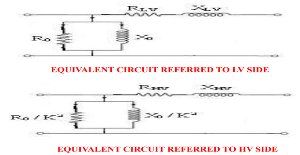
By the equivalent circuit parameters \( R_0, X_0, R_{01}, R_{02}, X_{01} \) and \( X_{02} \) are found from the O.C. and S.C. test results, draw the equivalent circuit referred to L.V. side as well as H.V. side.
Primary is L.V. side:
Secondary is H.V. side:
METER DESIGNING:
EQUIVALENT CIRCUIT OF TRANSFORMER:
With transformer parameter values obtained OC and SC tests, fill in the values in the equivalent circuits
CALCULATIONS OF EFFICIENCY & REGULATION:
- Copper losses = \( W_{SC} \times \left( \frac{1}{2} \right)^2 \) watts, where \( W_{SC} \) = full load copper losses
- Constant losses = \( W_0 \) watts
- Output = ½ KVA x \( \cos \phi \) ( \( \cos \phi \) may be assumed)
- Input = Output + Copper Loss + Constant loss
EFFICIENCY Vs LOAD CHARACTERISTICS:
At 0.8 Pf lag
Output P0 = K × (Rated KVA) × (0.80)
Iron loss (Constant loss) = Pi = W0
Copper loss = K2 PC = K2 Wsc
Where Wsc at rated current = copper loss at rated = Irated2 × Requ
Total loss = PL = (Pi + K2 PC)
Input power (Pinput) = P0 + PL = K × (rated KVA) × (0.8) + Pi + K2 PC
Efficiency = η = output / input
TABULATION:
| S.No | 1 | 2 | 3 | 4 | 5 | 6 | 7 | 8 |
|---|---|---|---|---|---|---|---|---|
| Different Transformer Loading (K) | 0.15 | 0.30 | 0.45 | 0.60 | 0.75 | 0.90 | 1.05 | 1.20 |
| Copper Losses (K2PC) | ||||||||
| Iron Losses (Pi) / Constant Losses | ||||||||
| Total loss = PL = (Pi + K2PC) | ||||||||
| Output Power (P0) in KW |
REGULATION Vs POWER FACTOR:
Determine the following either on LV or HV side
Rated voltage V = R=
Rated current I = X =
| Power Factor | 1.0 | 0.8 | 0.6 | 0.4 | 0.2 |
|---|---|---|---|---|---|
| R cos ɸ | |||||
| X sin ɸ | |||||
| R cos ɸ + X sin ɸ | |||||
| R cos ɸ - X sin ɸ | |||||
| Regulation (LAG) | |||||
| Regulation (LEAD) |
Mark the power factor corresponding to zero voltage regulation.
MODEL GRAPHS:
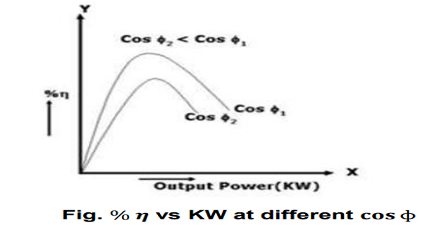
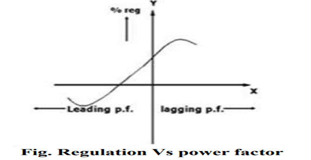
GRAPHS:
Plots should be drawn between
- % efficiency Vs output
- % regulation Vs power factor
DATA PROCESSING:
- \( Y_0 = \frac{I_0}{V_0} \)
- \( G_i = \frac{W_0}{(V_0)^2} \)
- \( B_m = \sqrt{Y_0^2 - G_i^2} \)
- \( Z_{eq} = \frac{V_{sc}}{I_{sc}} \)
- \( R_{eq} = \frac{W_{sc}}{(I_{sc})^2} \)
- \( X_{equ} = \sqrt{Z_{eq}^2 - R_{eq}^2} \)
DRAW THE EQUIVALENT CIRCUIT:
Draw the Equivalent circuit referred to the LV side & HV side.
RESULT & QUESTIONS:
RESULT:
- Equivalent circuit parameters referred to low voltage side and high voltage side.
-
PF at which regulation is zero =
| LOAD | EFFICIENCY |
| 1/4 | |
| 1/2 | |
| 3/4 | |
| FULL |
QUESTIONS:
- What are the losses of transformers?
- Why an LPF wattmeter is required in OC test?
- Can the regulation become zero? If so, under what conditions ?
- What are the advantages of performing the OC and SC test on transformer?