OBJECTIVE:
To study parallel operation of two single – phase transformers.
|
NAME PLATE DETAILS OF TRANSFORMERS |
||
|
|
TRANSFORMER 1 |
TRANSFORMER 2
|
|
KVA Rating |
1 KVA |
2 KVA |
|
H.V Voltage |
230 V |
230 V |
|
L.V Voltage |
115 V |
115 V |
|
H.V Current |
4.34 A |
8.6 A |
|
L.V Current |
8.69 A |
17.3 A |
|
Winding type |
Core |
Core |
APPARATUS REQUIRED:
|
S.No. |
Name of the Equipment |
Range |
Quantity |
Type |
|
1. |
Voltmeter |
300 V |
1 No |
Digital |
|
2. |
Voltmeter |
600 V |
1 No |
Digital |
|
3. |
Ammeter |
20 A |
3 Nos |
Digital |
|
4. |
Wattmeter |
150/300V 20A |
3 Nos |
Digital |
|
5. |
Single phase variac |
0-240V 20A |
1 No |
Core |
|
6. |
Resistive Load |
20 A |
1 No |
|
THEORY:
- A power transformer most vital and an equally expensive component in a power system.
- Over time, due to load growth in its service area, an existing transformer may not be able to withstand the demand during peak-hours without exceeding its long-term MVA rating.
- Operating a transformer in such a fashion would cause overheating and degrade its expected life.
- In most cases, instead of commissioning an entirely new higher capacity unit, a more viable alternative exists in adding a smaller unit in parallel to complement the existing one.
- In other words, a new smaller capacity transformer can now be connected in parallel to the existing one such that the two share a large peak load in a specific proportion and the one operating near limits is relieved of the burden.
- Also, during light load conditions, the additive capacity can be kept offline, if desired.
- To successfully operate the transformers in parallel, While commissioning, certain rules must be followed. We state them below, as applied to the single Phase transformers used in the experiment.
REQUIREMENTS FOR PARALLEL OPERATION:
Transformers getting connected in parallel are excited using same rated primary voltage source, then the following prerequisites must be met:
- Polarities of corresponding primary and secondary terminals of the two transformers must be same.
- No-load primary and secondary voltages of the two transformers should match closely in magnitude as well as in phase.
- Per unit impedances of two transformers on their respective Zbase must be equal if the transformers have to share the load in proportion to their ratings.
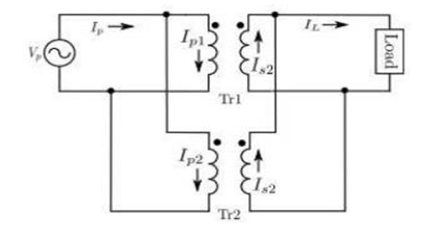
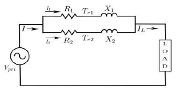
EQUIVALENT CIRCUIT OF PARALLEL TRANSFORMERS
- Equivalent circuit of transformer is shown with all quantities referred to the primary side. Also note that all quantities are in complex numbers unless specified otherwise
- Under parallel operation, the two
transformers would share the total load
current as indicated,
$$\begin{aligned} I_L & = I_1 + I_2 \\ I_1 & = \dfrac{Z_2 \times I_L}{Z_1+Z_2} \\ I_2 & = \dfrac{Z_1 \times I_L}{Z_1 + Z_2} \\ Z & = R+jX \end{aligned}$$
- If the phase angles of Z1
and Z2 are exactly matched, the magnitudes of
transformer currents are in inverse proportion to the respective transformer
equivalent leakage impedances
$$\dfrac{|I_1|}{|I_2|} = \dfrac{|Z_2|}{|Z_1|}$$
- This can be further extended to determine the power sharing between transformers.
- Consider two transformers of different MVA ratings connected in parallel with
the same voltage ratings. It is desirable that they share the load in proportion of
their MVA ratings. Hence we have in absolute scale (not in per unit),
$$\frac{S_1^*}{S_2^*}=\frac{I_1V_1^*}{I_2V_2^*}$$
- Dividing both sides by respective transformer MVA ratings and considering
that voltage ratings are equal, we have in per unit scale
$$\frac{|S_1|}{|S_2|}=\frac{|I_1|}{|I_2|}=\frac{|Z_2|}{|Z_1|}=1$$
- Note that, after dividing the proposed power sharing by respective ratings of the transformers, the share ratio becomes unity. Now, we conclude that, the per unit impedances of the two units must be equal for this type of power sharing.
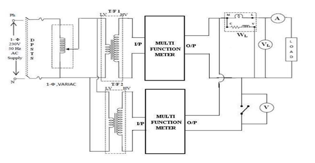
CIRCUIT DIAGRAM:
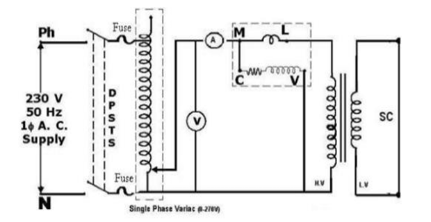
CIRCUIT DIAGRAM FOR SHORT CIRCUIT TEST:
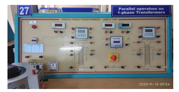
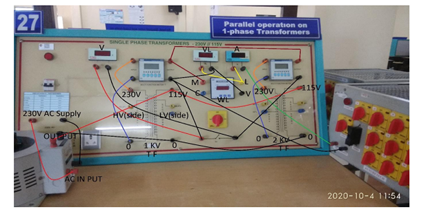
EM LAB SET-UP:
CONNECTION FOR PARALLEL OPERATION:
- Supply Positive Terminal (R) to Single Phase Auto Verica Input (R)
- Supply Negative Terminal (B) to Single Phase Auto Verica Input (B)
- Single Phase Auto Verica Output Positive Terminal (R) to LV Side (T/F-1) 115(R)
- Single Phase Auto Verica Output Positive Terminal (R) to LV Side Single (T/F-1) 115(R)
- Phase Auto Verica Output Terminal (B) to LV Side ( T/F-1 ) 0 (B)
- Single Phase Auto Verica Output Terminal (B) to LV Side ( T/F-2 ) 0 (B)
- T/F -1 HV Side 230 (R) to Input Terminal (R) Multi-Function meter(1)
- T/F -1 HV Side 0 (B) to Input Terminal (B) Multi-Function meter(1)
- Multi-Function meter(1) Output Terminal(R) Wattmeter M
- Multi-Function meter(1) Output Terminal(R) to Multi-Function meter(2) Output (R)
- Wattmeter L to Ammeter(R)
- Wattmeter L to Voltmeter (0)
- Ammeter (B) to Load (R)
- Multi-Function meter(1) Output Negative(B) to Watt meter V
- Multi-Function meter(1) Output Negative(B) to Voltmeter (300V)
- M/F meter(1) Output Negative(B) to Load (B)
- M/F meter(1) Output Negative(B) to Switch Terminal
- Switch Terminal to Voltmeter (0)
- M/F meter(2) Output Negative(B) to Switch Terminal
- Switch Terminal to Voltmeter (600)V
- Supply Positive Terminal (R) to Single Phase Auto Verica Input (R)
- Supply Negative Terminal (B) to Single Phase Auto Verica Input (B)
- Single Phase Auto Verica Output Positive Terminal (R) to LV Side (T/F-1) 115(R)
- Single Phase Auto Verica Output Positive Terminal (R) to LV Side Single (T/F-1) 115(R)
- Phase Auto Verica Output Terminal (B) to LV Side ( T/F-1 ) 0 (B)
- Single Phase Auto Verica Output Terminal (B) to LV Side ( T/F-2 ) 0 (B)
- Supply Positive Terminal (R) to Single Phase Auto Verica Input (R)
- Supply Negative Terminal (B) to Single Phase Auto Verica Input (B)
- Single Phase Auto Verica Output (R) to Input (R) Multi-Function meter
- Single Phase Auto Verica Output (B) to Input (B) Multi-Function meter
- Multi-Function meter Output (R) to T/F -2 HV Side 230 (R)
- Multi-Function meter Output (B) to T/F -2 HV Side 0 (R)
- LV Side T/F -2 (R)115 V to LV Side T/F-2(B) 0
PROCEDURE:
- Connections are made according to circuit diagram.
- The single phase variac should be in minimum output position.
- Switch on the 1- ɸ supply. Slowly increase the variac to get the rated voltage. The voltmeter across the switch should read zero then close the switch.
- If the voltmeter does not read zero interchange the terminals of secondary of any one transformer and repeat the step-3.
- By loading the transformers in steps note down the values of current, Voltage, Power from the Multifunction meters of the two transformers. Note down VL, IL, WL from the meters connected to load. The load is applied up to full rated current. Note all the values in the observation table.
- Reduce the load on transformer, bring back to variac in minimum output position and switch off the 1- ɸ supply.
- Connections are made as shown for both transformers separately.
- Conduct short-circuit test (by increasing the current to rated value with the help of variac) on each of the single-phase transformers separately to determine their Req, Xeq, and Zeq (series parameters of the equivalent circuit) values.
OBSERVATION TABLE:
- Measured Voltage, Current and Power:-
Applied voltage = Applied Frequency =
- Short Circuit test of two transformers:-
|
S. No |
VSC1 (V) |
ISC1 (A) |
Wsc1 = W x M. F (W) |
VSC2 (V) |
ISC2 (A) |
WSC2= W x M.F (W) |
|
|
|
|
|
|
|
|
CALCULATION:
- Measured and estimated KVA loads and power factors of transformers
Applied voltage = Z1 = Z2 =
Using Z1 and Z2 in equation and estimate how load is shared.
- Calculation of Req, Xeq, and Zeq for both transformers as it was done in previous experiment.
- Calculation of power factor for both transformers under different load conditions.
RESULT & QUESTIONS:
RESULT:
- Compare load distribution of both transformers (current, active power and reactive power) with respect to series parameters of transformers.
- Compare power factors of both transformers.
QUESTIONS:
- What is the significance of the polarity of the transformer windings?
- What is the effect of difference in voltage ratings of the secondaries?
- What are the essential and desirable conditions for parallel operation of transformers?