Demonstrative Video
OBJECTIVE:-
To study the performance of the Scott connected transformers on no-load and full load.
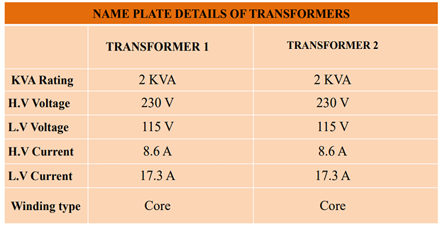
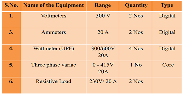
APPARATUS REQUIRED:
MOTIVATION:
- Sometimes two-phase electric equipment like an electric arc furnace or two-phase induction motors used in servo applications might need a two phase supply whereas only a three-phase supply may be available.
- This problem can be tackled by means of Scott connected transformer which converts a balanced three-phase supply to a balanced two-phase supply.
- Such a connection can also supply a single phase load by suitably connecting the secondary windings of the two phase system without creating an imbalance in the three phase system.
THEORY:
- The Scott-T Connection is the method of connecting two single phase transformer to perform the 3-phase to 2-phase conversion and vice-versa.
- The two transformers are connected electrically but not magnetically. One of the transformer is called the main transformer, and the other is called the auxiliary or teaser transformer.
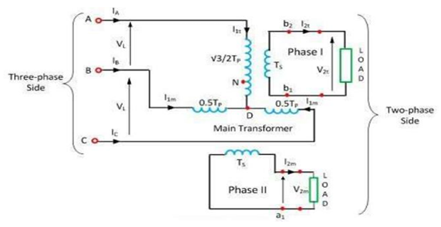
- The figure below shows the Scott-T transformer connection
- The main transformer is center tapped at D and is connected to the line B and C of the 3-phase side. It has primary BC and secondary a1a2
- The teaser transformer is connected to the line terminal A and the center tapping D. It has primary AD and the secondary b1b2
- The identical, interchangeable transformers are used for Scott-T connection in which each transformer has a primary winding of Tp turns and is provided with tapping at 0.289Tp, 0.5Tp, and, 0.866Tp
PHASOR DIAGRAM OF SCOTT CONNECTION TRANSFORMER:
- The line voltages of the 3-phase system VAB, VBC, and VCA which are balanced are shown in the figure below. The same voltage is shown as a closed equilateral triangle.
- The figure below shows the primary winding of the main and the teaser transformer.
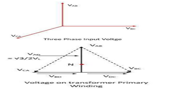 ∣VAB∣ = ∣VBC∣ = ∣VCA∣ = ∣VL∣
 - The D divides the primary BC of the main transformers into two halves and hence the number of turns in portion BD = the number of turns in portion DC = Tp/2.
- The voltage VBD and VDC are equal, and they are in phase
with VBC.
$$V_{BD}=V_{DC}=\frac{1}{2}V_{BC}=\frac{1}{2}V_L <0^0$$
- The voltage between A and D is
$$\begin{aligned} &V_{BD}=V_{DC}=\frac{1}{2}V_{BC}=\frac{1}{2}V_{L} <0^{0} \\ &V_{AD}=V_{BD}+V_{AB} \\ &V_{AD}=V_{L} \left(\frac{-1}{2}+j \frac{\sqrt{3}}{2}\right)+\frac{1}{2} V_{L} \\ &V_{AD}=V_{L} \left(j \frac{\sqrt{3}}{2}\right)=0.866 V_{L}<90^{0} \end{aligned}$$
- The teaser transformer has the primary voltage rating that is \(\frac{\sqrt{3}}{2}\) of the voltage ratings of the main transformer.
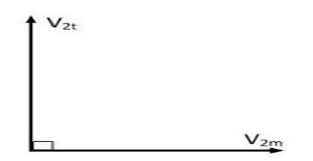
- Voltage VAD is applied to the primary of the teaser transformer and therefore the
secondary of the voltage V2t of the teaser transformer will lead the secondary
terminal voltage V2m of the main transformer by 90o as shown in the figure below.
$$\frac{V_{S_{1}}}{V_{AD}}=\frac{T_{S}}{T_{AD}}\\V_{2t}=\frac{T_{S}}{T_{AD}}V_{AD}=\frac{T_{S}}{\frac{\sqrt{3}}{2}T_{P}}\mathbf{x}\frac{\sqrt{3}V_{t}}{2}\\\frac{T_{S}}{T_{L}}V_{L}=V_{2m}$$ - For keeping the voltage per turn same in the primary of the main transformer and
the primary of the teaser transformer, the number of turns in the primary of the
teaser transformer should be equal to .$${\frac{\sqrt{3}}{2T_{p}}}$$
- Thus, the secondaries of both transformers should have equal voltage ratings. The V2t and V2m are equal in magnitude and apart in time; they result in the balanced 2-phase system.
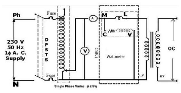
CIRCUIT DIAGRAM:
- Let V be the primary line to line voltage and N1, N2 be the no. of turns in the primary and secondary respectively, then the secondary voltage will be \(V\cdot \left( \dfrac{N_2}{N_1}\right)\).
- The active number of turns in the main transformer’s primary N1 and the teaser transformer primary is \(\left(\dfrac{\sqrt{3}}{2}\right)N_1\).
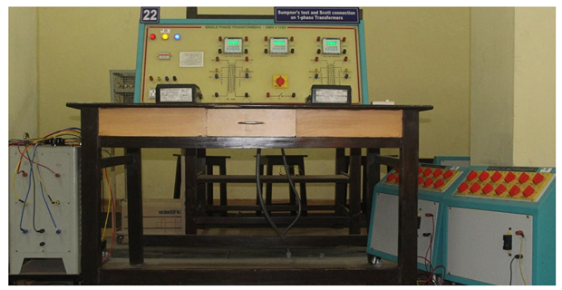
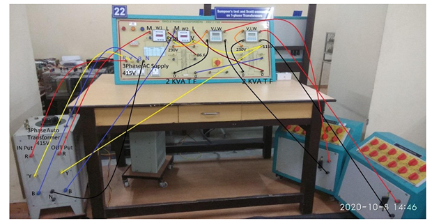
EM LAB SET-UP:
CONNECTION FOR SCOTT OPERATION OF TRANSFORMERS:
- 3ɸAC Supply R to 3ɸ Auto Verica Input Terminal R
- 3ɸ AC Supply Y to 3ɸ Auto Verica Input Terminal Y
- 3ɸ AC Supply B to 3ɸ Auto Verica Input Terminal B
- 3ɸ Auto Verica Output R to Wattmeter(1) Terminal M
- Wattmeter Terminal L to LV Side Transformer(1) 86.6%
- 3ɸ Auto Verica Output Y to LV Side Transformer(2) Terminal 115 V
- 3ɸ Auto Verica Output B to Wattmeter(2) Terminal M
- Wattmeter(2) Terminal L to LV Side Transformer(2) Terminal 0
- Wattmeter(1) Terminal V to Wattmeter(2) Terminal V
- Wattmeter(2) Terminal V to LV Side Transformer(2) Terminal 115 V
- LV Side Transformer(1) Terminal 0 to LV Side Transformer(2) Terminal 50%
- HV Side Transformer(1) Terminal 230V to Input Multifunction meter(1) Terminal(R)
- HV Side Transformer(1) Terminal 0 to Input Multifunction meter(1) Terminal(B)
- Multifunction meter (1) Output Terminal(R) to Resistive Load Terminal(R)
- Multifunction meter (1) Output Terminal(B) to Resistive Load Terminal(B)
- HV Side Transformer(2) Terminal 230V to Input Multifunction meter(2) Terminal(R)
- HV Side Transformer(2) Terminal 0 to Input Multifunction meter(2) Terminal(B)
- Multifunction meter (2) Output Terminal(R) to Resistive Load Terminal(R)
- Multifunction meter (2) Output Terminal(B) to Resistive Load Terminal(B)
PRECAUTIONS:
- Connections must be made tight.
- Before making or breaking the circuit, supply must be switched off.
PROCEDURE:
- Connect the circuit.
- Keep the 3 phase auto-transformer in minimum output position and switch on the 3- phase supply.
- Apply rated voltage to the primary windings of Main and Teaser transformers with the help of the three phase auto - transformer.
- Apply load on the transformers up to full load current. By loading the Transformers in steps note down the VL, IL, W from multifunctional meter and Input wattmeter readings. Also, take Input current reading on the 3-phase side. (it should be 1.15 times ILoad).
- After taking the meter readings remove the load on the transformer.
- Bring back the auto transformer to its minimum output position and switch off the 3- phase supply.
OBSERVATION TABLE:
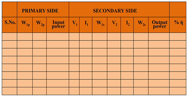
FORMULAE:
$$\begin{aligned}&\mathrm{Input~Power~(~P_i~)=W_{lp}+W_{2p}}\\&\mathrm{Output~Power~(~P_0)=V_1*I_1+V_2*I_2}\\&\text{Efficiency}=\text{Output
Power ( P}_0)/\text{Input Power (
P}_\mathrm{i})\end{aligned}$$
MODEL GRAPH:
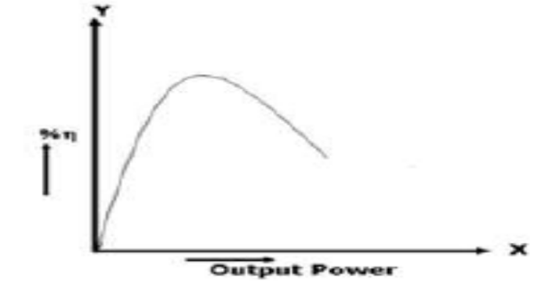
- Draw the graph Efficiency Vs Output
RESULT & QUESTIONS:
RESULT:
QUESTIONS:
- What are the applications of Scott connection?
- If the currents in the 2-phase side are unbalanced what will be its effect on the 3-phase side?
- How will you find out the phase shift between the two secondary voltages in Scott connection (This was not done in your experiment)?