NO LOAD TEST ON DC SHUNT MOTOR
Demonstrative Video
Theoretical Explanation
Experiment
OBJECTIVE FOR NO LOAD TEST (SWINBURNE’S TEST):-
To pre-determine the efficiency of a DC shunt machine when run both as generator and motor.
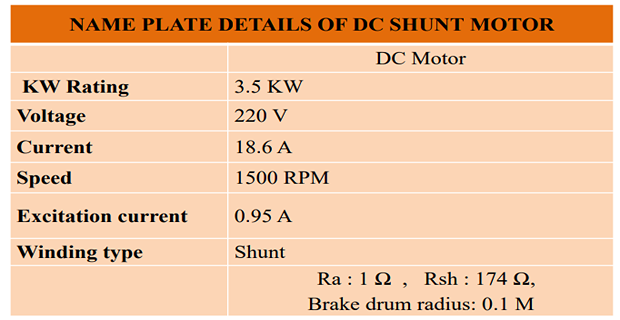
NAME PLATE DETAILS:
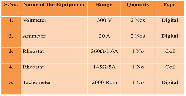
APPARATUS REQUIRED
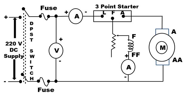
CIRCUIT DIAGRAM FOR NO LOAD TEST
INTRODUCTION & THEORY:
- Testing of a DC motor is given by,
- The various losses taking place in a d.c. motor and efficiency can be
calculated by carrying out test on d.c. motors. There are different
methods of testing d.c. motors. These methods are broadly classified as:
- Direct method of testing
- Indirect method of testing
\(\text{Efficiency}=\frac{\text{Power output}}{\text{Power input}}=\frac{\text{Power input}-\text{Losses}}{\text{Power input}}\)
INDIRECT METHOD OF TESTING
SWINBURNE’S TEST OR NO LOAD TEST
- In these methods the motor is not loaded directly but the losses and efficiency at different loads can be estimated or predetermined.
- Out of the different methods available for testing of d.c. motors, Swinburne’s test and Hopkinson’s test are commonly used in practice for shunt-motors.
- Swinburne’s test is a no-load test on a dc machine. This is indirect method of testing d.c. motors in which flux remains practically constant i.e. specially in case of shunt and compound motors.
- The machine is started and run as a motor with shaft decoupled from any load. The motor is run on no load at its rated voltage and rated speed.
- At the starting some resistance is connected in series with the armature which is cut when motor attains sufficient speed. Now the speed of the motor is adjusted to the rated speed with the help of shunt field rheostat.
- Without actually loading the motor, the losses and hence efficiency at different loads can be found out. In this regard the test is very easy to carry out for a machine of any size, particularly convenient for a large machine.
LOSSES IN A D.C. MACHINE:
The various losses in a d.c. machine whether it is a motor or a generator are classified into three groups as:
- Copper losses
- Iron (or) core losses
- Mechanical losses
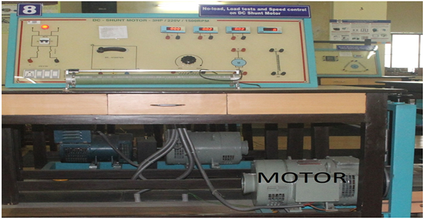
EM LAB SET-UP:
PRECAUTIONS
- Starter arm must be in OFF position.
- Motor field rheostat must be kept in minimum resistance position.
- Motor should be started and stopped under no load condition.
- Brake drum should be cooled with water when it is under load.
CONNECTION
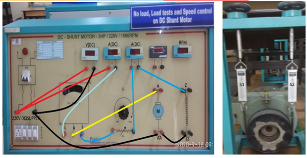
- Supply Positive to Ammeter (1) Terminal (Red)
- Supply Positive to Voltmeter Terminal (Red)
- Ammeter Terminal (Black) to 3 Point Starter L
- 3 Point Starter F to Rheostat Terminal (Red)
- Rheostat Terminal (Red) to Ammeter Terminal (Red)
- Ammeter Terminal (Black) to Field Terminal Z
- 3 Point Starter A to Motor A
- Supply Negative Terminal (Black) to Voltmeter Terminal (Black)
- Supply Negative Terminal (Black) to Motor Field Terminal ZZ
- Motor Field Terminal ZZ to Motor Armature Terminal AA
PROCEDURE:
- Connect the circuit.
- Motor field rheostat must be kept in minimum resistance position.
- Switch on MCB, Start the motor with the help of 3 point starter.
- Vary the field rheostat to adjust the speed of motor to 1500 rpm.
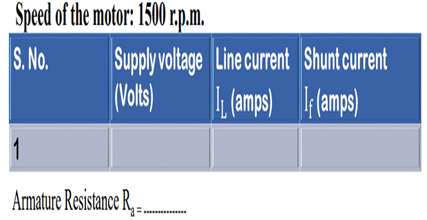
- Note down the value of Voltmeter (V), Line or Armature Current (IL), and field current (If).
- Bring the field rheostats to initial position as in step 2. Switch off the MCB.
- Measure the armature resistance of the DC shunt motor.
OBSERVATION:
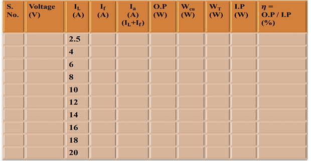
CALCULATION (WHEN MACHINE RUN AS MOTOR)
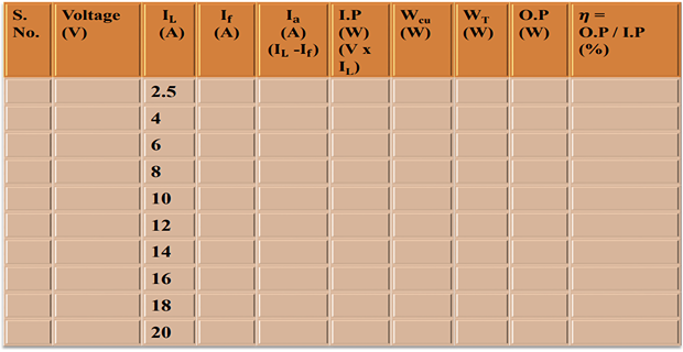
CALCULATION (WHEN MACHINE RUN AS GENERATOR):-
MODEL CALCULATIONS
MACHINE WHEN RUN AS MOTOR:
MACHINE WHEN RUN AS GENERATOR:
MODEL GRAPH:-
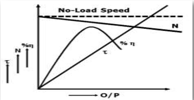
- Plots are drawn between:
- Motor Efficiency Vs Output of motor.
- Generator Efficiency Vs Output of generator.
RESULT
Write the conclusions and inferences obtained from this experiment.
LOAD TEST ON DC SHUNT MOTOR
OBJECTIVE FOR LOAD TEST
To obtain the performance characteristics of DC shunt motor by direct loading.
CIRCUIT DIAGRAM FOR LOAD TEST
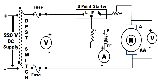
LOAD TEST ON DC SHUNT GENERATOR:-
INTRODUCTION
- This is a direct method of testing motor.
- In this method, the motor is put on the direct load by means of a belt and pulley arrangement. By adjusting the tension of belt, the load is adjusted to give the various values of currents. The load is finally adjusted to get full load current.
- The power developed gets wasted against the friction between belt and shaft. Due to the braking action of belt, the test is called brake test.
CONNECTION
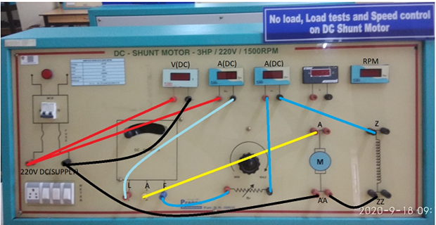
- Supply Positive to Ammeter Terminal (Red)
- Supply Positive to Voltmeter Terminal (Red)
- Ammeter Terminal (Black) to 3 Point Starter L
- 3 Point Starter F to Rheostat Terminal (Red)
- Rheostat Terminal (Black) to Field Terminal Z
- 3 Point Starter A to Motor A
- Supply Negative Terminal (Black) to Voltmeter Terminal (Black)
- Supply Negative Terminal (Black) to Motor Field Terminal ZZ (Black)
- Motor Field Terminal ZZ (Black) to Motor Armature Terminal AA (Black)
PROCEDURE
- Connect the circuit.
- Motor field rheostat must be kept in minimum resistance position.
- Switch on MCB, Start the motor with the help of 3 point starter.
- Vary the field rheostat to adjust the speed of motor to 1500 rpm.
- Load the motor in steps by tightening the brake drum belt and note S1 and S2 from the spring balance weight, meters \( V_L, I_L \), speed till the rated current is reached.
- Remove the load on the motor until S1 and S2 read zero.
- Bring back the field rheostat to initial position, as in step 2. Switch OFF the MCB.
- Measure the effective diameter of the drum.
OBSERVATION TABLE
Radius of the brake drum = ------------m
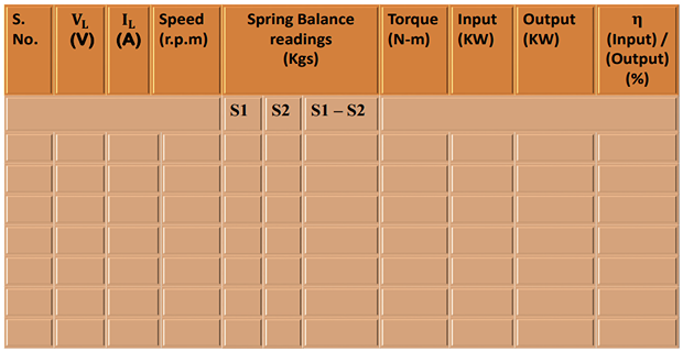
FORMULAS
MODEL GRAPH
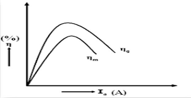
- Plots drawn between
- % efficiency vs Output
- Speed vs Output
- Torque vs Output
RESULT
Write the conclusions and inferences obtained from this experiment.
SPEED CONTROL OF DC SHUNT MOTOR:
OBJECTIVE FOR LOAD TEST:
To obtain the speed characteristics of DC shunt motor by
- Armature control method.
- Field control method.
CIRCUIT DIAGRAM FOR LOAD TEST:-
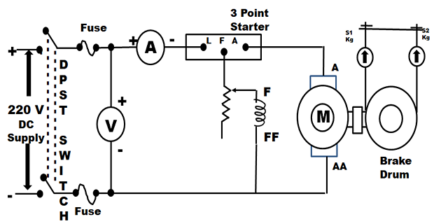
INTRODUCTION
- Speed of a Shunt DC motor can be easily controlled. Despite the load changes, Shunt DC motor can maintain constant speed.
- When the load increases the armature tends to slow down. This results in less back EMF. This accounts for less opposition against the supplied voltage. So, the motor will draw more current.
- This increase in current results in increase in torque to gain speed. Thus, even when the load increases, the net effect of load on speed in a Shunt DC motor is almost nil.
- When the load decreases, armature gains speed and generates more back EMF. As the polarity of the back EMF is against the supply voltage, load reduction results in less current and hence speed is maintained constant.
- Shunt DC motors are very suitable for belt-driven applications. This constant speed motor is used in industrial and automotive applications where great amount of torque precision is required.
-
The DC motors are in general much more adaptable speed drives than the AC motors. The speed of the DC motors depends upon the following relation:
- \( n = K_n \cdot \frac{V_a - I_a R_a}{\phi} \) (\( V_a \) = Voltage across armature terminals)
-
Armature voltage drop (\( I_a R_a \)) is quite small and can be ignored. Thus,
\[ n = K_n \cdot \frac{V_a}{\phi} \]as per the magnetization characteristic \(\phi \propto I_f\)\[ n = K_n \cdot \frac{V_a}{I_f} \]In the linear region of the magnetization characteristic \(\phi \propto I_f\) and so\[ n = K'_n \cdot \frac{V_a}{I_f} \]
The equation gives two methods of speed control:
- Variation of field excitation (keeping \( V_a \) constant): Field Control.
- Variation of voltage across armature (\( V_a \)) (keeping field current constant): Armature Control.
THEORY:
a) VARIATION OF FLUX OR FLUX CONTROL METHOD:
- By decreasing the flux, the speed can be increased and vice versa.
- The flux of a DC motor can be changed by changing the field current (\( I_{sh} \) or \( I_f \)) with the help of a shunt field rheostat.
- Since \( I_{sh} \) is relatively small, the shunt field rheostat has to carry only a small current, which means \( I_{sh}^2 \cdot R_{sh} \) loss is small.
b) ARMATURE OR RHEOSTATIC CONTROL METHOD:
- This method is used when speeds below the no-load speed are required.
- As the supply voltage is normally constant, the voltage across the armature is varied by inserting a variable rheostat in series with the armature circuit.
- As controller resistance is increased, voltage across the armature is decreased, thereby decreasing the armature speed.
- For a load constant torque, speed is approximately proportional to the voltage across the armature.
- From the speed/armature current characteristic, it is seen that greater the resistance in the armature circuit, greater is the fall in the speed.
CONNECTIONS
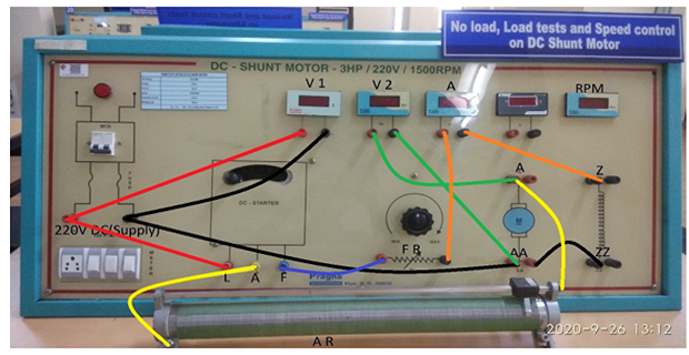
- Supply Positive to 3 Point Starter Terminal L
- Supply Positive to Voltmeter Terminal (Red)
- 3 Point Starter F to Rheostat (1) Terminal (Red)
- Rheostat Terminal (Red) to Ammeter Terminal (Red)
- Ammeter Terminal (Black) to Field Terminal Z
- 3 Point Starter A to Rheostat (2) Terminal (Red)
- Rheostat (2) Terminal (Black) to Motor Terminal A
- Supply Negative Terminal (Black) to Voltmeter Terminal (Black)
- Supply Negative Terminal (Black) to Motor Field Terminal ZZ (Black)
- Motor Field Terminal ZZ (Black) to Motor Armature Terminal AA (Black)
- Motor Terminal A to Voltmeter (2) Terminal (Red)
- Motor Terminal AA to Voltmeter (2) Terminal (Black)
PROCEDURE
ARMATURE CONTROL METHOD:
- Connect the circuit.
- Motor field rheostat must be kept in minimum resistance position.
- Armature rheostat should be kept in minimum resistance position.
- Switch on MCB, start the motor with the help of 3 point starter.
- Vary the field rheostat to adjust the speed of motor to 1500 rpm.
- For If ________ (value obtained at rated speed), vary the Va with the help of armature rheostat resistance and note down the armature voltage and speed readings. (Speed of the motor should not be less than 1000 rpm).
- Bring the armature and field rheostats to initial position as in steps 2 and 3, switch off the MCB.
FIELD CONTROL METHOD:
- Connect the circuit.
- Motor field rheostat must be kept in minimum resistance position.
- Armature rheostat should be kept in minimum resistance position.
- Switch on MCB, start the motor with the help of 3 point starter.
- Vary the field rheostat to adjust the speed of motor to 1500 rpm.
- For \( V_a \) ________ (value obtained at rated speed), vary the \( I_f \) with the help of field rheostat resistance and note down the speed and ammeter readings. (Speed of the motor should not be more than 1750 rpm).
- Bring the armature and field rheostats to initial position as in steps 2 and 3, switch off the MCB.
OBSERVATION TABLE
ARMATURE CONTROL METHOD:-
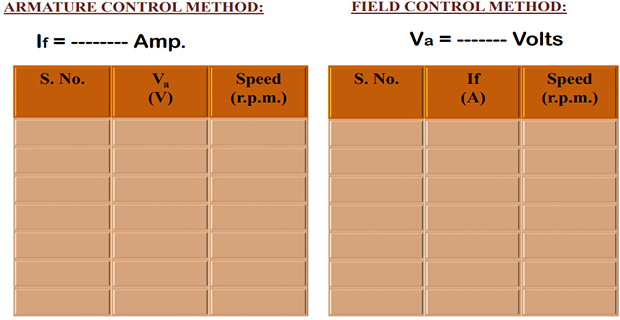
MODEL GRAPH:-
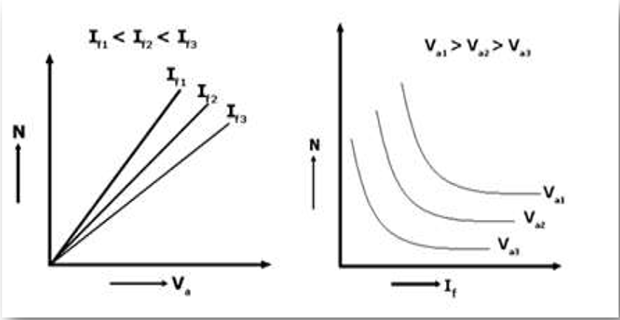
FIELD CONTROL METHOD ARMATURE CONTROL METHOD
GRAPHS:-
- Plots are drawn between:
- Armature Voltage Vs Speed
- Field Current Vs Speed
RESULT & QUESTIONS:-
RESULT:-
Hence speed characteristics of a DC shunt motor by
- Armature control method
- Field control method graph are plotted.
QUESTIONS:
- What are the advantages and disadvantages of performing Swinburne’s test on DC shunt machine?
- What is the difference in the performance characteristic (Efficiency Vs. output) of the DC machine obtained in Swinburne’s test and load test?
- What is the three point starter and what are its advantages?
- Which method is best suited for speed control and give a few applications?