Three-Phase Circuits
Problem-1: Line and Phase Quantities
Determine the following quantities for the circuit shown
line currents
phase voltages of the load
line voltages of the load
phase voltages of the source
line voltages of the source
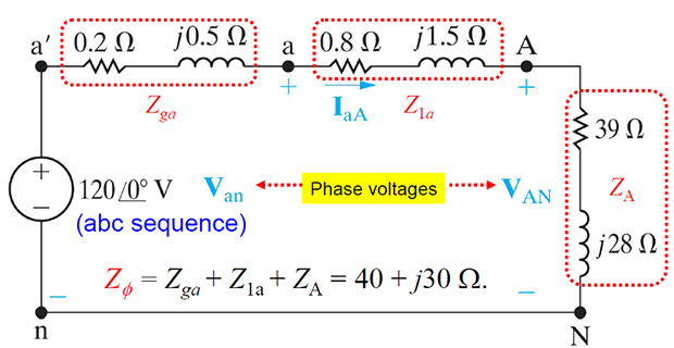
Solution-1
The 3 line voltages of the load are:
Problem-2: Complex power and Power Dissipation
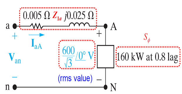
Solution-2
Problem-3: Star and Delta Configurations
Each phase of a three-phase alternator, generates a voltage of 3810.5 V and can carry a maximum current of 30 A.
Find the following quantities:
line current,
line voltage
total kVA capacity,
if the alternator is connected in
star configuration
delta configuration
Solution-3
\(\text { Given data: }~~ E_{p h}=3810.5 \mathrm{V} ~~ I_{p h}=30 A\)
| Star | Delta |
|
\[\begin{aligned}
\Rightarrow & \text{Line current}~ \mathrm{I}_{t}
=\mathrm{I}_{\mathrm{ph}}=30 \mathrm{A} \\
\Rightarrow & \text{Line voltage} ~\mathrm{E}_{\ell} =\sqrt{3}
\mathrm{E}_{\mathrm{ph}}\\
& =6600 \mathrm{V} \\
\Rightarrow & \text{Total}~ \mathrm{kVA} =\sqrt{3} \mathrm{E}_{l}
\mathrm{I}_{l} \\
=&\sqrt{3} \times 6600 \times 30 \times 10^{-3} \\
&=342.95
\end{aligned}\] |
\[\begin{aligned}
\Rightarrow & \mathrm{I}_{\ell}=\sqrt{3}
\mathrm{I}_{\mathrm{ph}}=51.96 \mathrm{A} \\
\Rightarrow & \mathrm{E}_{\ell}=3810.5 \mathrm{V} \\
\Rightarrow & \text { Total kVA }=\sqrt{3} \mathrm{E}_{l}
\mathrm{I}_{l} \\
=&\sqrt{3} \times 3810.5 \times 51.96 \times 10^{-3} \\
&=342.95
\end{aligned}\] |
Problem-4: Balanced 3-phase System
A balanced \(3-\phi\) load connected in star consists of \((6 + j 8)~\Omega\) impedance in each phase. It is connected to a \(3-\phi\) supply of 400 V, 50 Hz.
Find the following quantities:
magnitude of phase current
magnitude of line current
per phase power
total power.
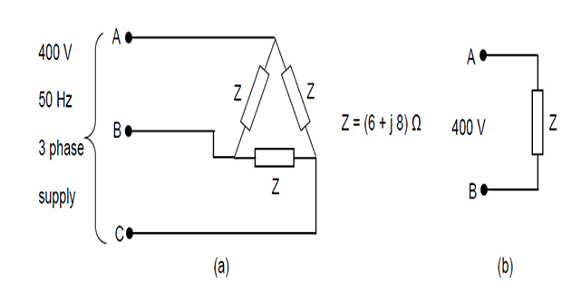
Repeat the problem with the load impedance connected in delta
Solution-4
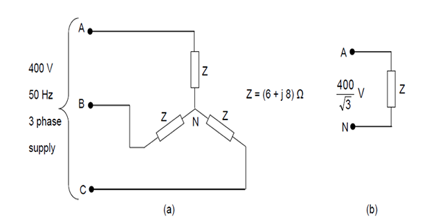
\(E_{p h}=400 ~\mathrm{V} \quad Z=(6+j 8) \Omega=10 \angle 53.13^{\circ} \Omega\)
Phase current, \(\mathrm{I}_{\mathrm{ph}}=400 / 10=40 \mathrm{A}\)
Line current, \(\mathrm{I}_{\ell}=\sqrt{3} \mathrm{I}_{\mathrm{ph}}=69.282 \mathrm{A}\)
Per phase power, \(P=E_{p h} I_{p h} \cos \theta=400 \times 40 \times \cos 53.13^{\circ}=9600 \mathrm{W}\)
Total power, \(\mathrm{P}_{T}=\sqrt{3} \mathrm{E}_{\ell} \mathrm{I}_{\ell} \cos \theta=\sqrt{3} \times 400 \times 69.282 \times \cos 53.13^{\circ}=28800 \mathrm{W}\)
Alternatively, total power, \(\mathrm{P}_{\mathrm{T}}=3 \mathrm{P}=28800 \mathrm{W}\)
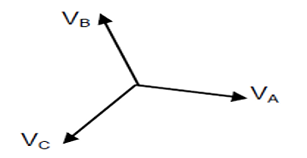
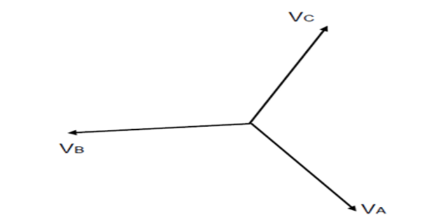
Problem-5: Phase Sequence
Solution-5
Problem-6: Balanced System & Phase Sequence
In a three-phase balanced supply, voltage \(\mathrm{V}_{\mathrm{C}}=110 \angle 65^{\circ} \mathrm{V}\).
Taking the phase sequence as \(\mathrm{ABC}\), find
the phase voltage
the line voltages
Solution-6
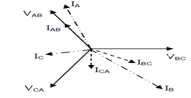
Problem-7: Unbalanced Delta System
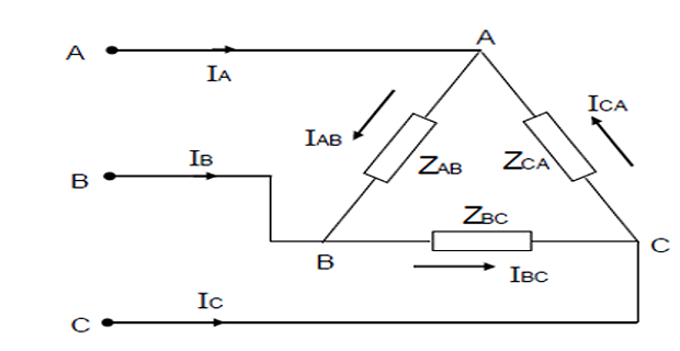
- line voltages
- phase currents
- line currents
- the real power consumed by the load.
Solution-7
\[\begin{aligned}
\mathrm{V}_{\mathrm{BC}}&=240 \angle 0^{\circ} \mathrm{V}\\
\mathrm{V} \mathrm{CA} & =240 \angle-120^{\circ} \mathrm{V}\\
\mathrm{V}_{\mathrm{AB}}&=240 \angle-240^{\circ} \mathrm{V}
\end{aligned}\] |
\[\begin{aligned}
\mathrm{Z}_{\mathrm{AB}}&=10 \angle 0^{\circ} \Omega \\
\mathrm{Z}_{\mathrm{BC}}&=10 \angle 30^{\circ} \Omega\\
\mathrm{Z}_{\mathrm{CA}}&=15 \angle-30^{\circ} \Omega
\end{aligned}\] |
Problem-8: Unbalanced Star System
A \(3-\phi\), 4 -wire, \(208~\mathrm{V}\) system has a star connected load with impedances
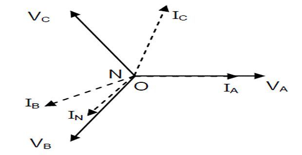
Taking the voltage \(\mathrm{V_{AN}}\) as reference, determine line and neutral currents. Draw the phasor diagram. Also calculate the real power consumed by the load.
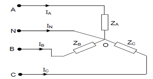
Solution-8
\(\mathrm{Z}_{\mathrm{A}}=6 \angle \mathrm{0}^{\circ} \Omega ;~ \mathrm{Z}_{\mathrm{B}}=6 \angle 30^{\circ} \Omega\); \(\mathrm{Z}_{\mathrm{C}}=5 \angle 45^{\circ} \Omega\)
Taking the phase sequence as ABC,
|
\[\begin{aligned}
\mathrm{V}_{\mathrm{AN}}&=\frac{208}{\sqrt{3}} \angle 0^{\circ} V\\
&=120.08 \angle 0^{\circ} \mathrm{V}\\
\mathrm{V}_{\mathrm{BN}}&=120.08 \angle-120^{\circ} \mathrm{V}\\
\mathrm{V}_{\mathrm{CN}}&=120.08 \angle-240^{\circ} \mathrm{V}
\end{aligned}\] |
\[\begin{aligned}
\mathrm{I}_{\mathrm{A}}&=\frac{\mathrm{V}_{\mathrm{AN}}}{\mathrm{Z}_{\mathrm{A}}}=\frac{120.08}{6
\angle 0^{\circ}}\\
&=20.01 \angle 0^{\circ} \mathrm{A}\\
\mathrm{I}_{\mathrm{B}}&=\frac{\mathrm{V}_{\mathrm{BN}}}{\mathrm{Z}_{\mathrm{B}}}=\frac{120.08
\angle-120^{\circ}}{6 \angle 30^{\circ}}\\
&=20.01 \angle-150^{\circ} \mathrm{A}\\
\mathrm{I}_{\mathrm{C}}&=\frac{V_{C N}}{Z_{C}}=\frac{120.08
\angle-240^{\circ}}{5 \angle 45^{\circ}}\\
&=24.01 \angle 75^{\circ} \mathrm{A}
\end{aligned}\] |
Resistances in different phases are:
\(\mathrm{R}_{\mathrm{A}}=6 \Omega ~~ \mathrm{R}_{\mathrm{B}}=6 \cos 30^{\circ}=5.1962 \Omega ~~ \mathrm{R}_{\mathrm{C}}=3.53 \Omega\)
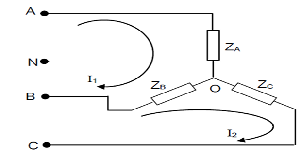
Problem-9: Unbalanced Systems
A \(3-\phi\), 3-wire, 208 V, ACB system has star connected load with impedances \(\mathrm{Z}_{\mathrm{A}}=6 \angle 0^{\circ} \Omega ; ~ \mathrm{Z}_{\mathrm{B}}=6 \angle 30^{\circ} \Omega\) and \(\mathrm{Zc}=5 \angle 45^{\circ} \Omega .\) Taking \(\mathrm{V}_{\mathrm{BC}}\) as reference, Determine
line currents
the voltage across load impedances
Solution-9
|
\[\begin{aligned}
\mathrm{V}_{\mathrm{BC}}&=208 \angle \mathrm{0}^{\circ} \mathrm{V}
\\ \quad \mathrm{V}_{\mathrm{CA}}&=208 \angle 120^{\circ} \mathrm{V}
\\ \quad \mathrm{V}_{\mathrm{AB}}&=208 \angle-120^{\circ} \mathrm{V}
\end{aligned}\] |
\[\begin{aligned}
Z_{A}&=6 \Omega \\
Z_{B}&=(5.1962+j 3) \Omega \\
Z_{C}&=(3.5355+j 3.5355) \Omega
\end{aligned}\] |
\(\left[\begin{array}{cc}Z_{A}+Z_{B} & -Z_{B} \\ -Z_{B} & Z_{B}+Z_{c}\end{array}\right]\left[\begin{array}{l}I_{1} \\ I_{2}\end{array}\right]=\left[\begin{array}{c}V_{A B} \\ V_{B C}\end{array}\right]\) \(\left[\begin{array}{cc}11.1962+j 3 & -5.1962-j 3 \\ -5.1962-j 3 & 8.7317+j 6.5355\end{array}\right]\left[\begin{array}{l}I_{1} \\ I_{2}\end{array}\right]=\left[\begin{array}{c}208 \angle-120^{\circ} \\ 208 \angle 0^{\circ}\end{array}\right]\)
Determinant of the coefficient matrix \(= 90.9323 \angle 48.580\)
\(\left[\begin{array}{l}\mathrm{I}_{1} \\ \mathrm{I}_{2}\end{array}\right]=\frac{1}{90.9323 \angle 48.58^{\circ}}\left[\begin{array}{cc}8.7317+\mathrm{j} 6.5355 & 5.1962+\mathrm{j} 3 \\ 5.1962+\mathrm{j} 3 & 11.1962+\mathrm{j} 3\end{array}\right]\left[\begin{array}{c}208 \angle-120^{\circ} \\ 208 \angle 0^{\circ}\end{array}\right]\) \(=\left[\begin{array}{c}-3.6097-\mathrm{j} 22.9799 \\ 11.7974-\mathrm{j} 23.7446\end{array}\right]=\left[\begin{array}{l}23.2617 \angle-98.93^{\circ} \\ 26.5139 \angle-63.58^{\circ}\end{array}\right]\)
\(\left[\begin{array}{l}\mathrm{I}_{1} \\ \mathrm{I}_{2}\end{array}\right]=\left[\begin{array}{l}-3.6097-\mathrm{j} 22.9799 \\ 11.7974-\mathrm{j} 23.7446\end{array}\right]\)
From the mesh currents, line currents can be calculated:
\(\mathrm{I}_{\mathrm{A}}=\mathrm{I}_{1}=(-3.6109-\mathrm{j} 22.9797) \mathrm{A}=23.2617 \angle-98.93^{\circ} \mathrm{A}\) \(\mathrm{I}_{B}=\mathrm{I}_{2}-\mathrm{I}_{1}=(15.4071-\mathrm{j} 0.7647) \mathrm{A}=15.426 \angle-2.84^{\circ} \mathrm{A}\) \(\mathrm{I_C}=-\mathrm{I}_{2}=(-11.7974+\mathrm{j} 23.7446) \mathrm{A}=26.5139 \angle 116.42^{\circ} \mathrm{A}\)
Voltages across the loads can be calculated as:
\(\mathrm{V}_{\mathrm{AO}}=\mathrm{Z}_{\mathrm{A}} \mathrm{I}_{\mathrm{A}}=(-21.6654-\mathrm{j} 137.8782) \mathrm{A}=139.5702 \angle-98.93^{\circ} \mathrm{V}\) \(\mathrm{V}_{\mathrm{BO}}=\mathrm{Z}_{\mathrm{B}} \mathrm{I}_{\mathrm{B}}=(82.3503+\mathrm{j} 42.2497) \mathrm{A}=92.556 \angle 27.16^{\circ} \mathrm{V}\) \(\mathrm{V}_{\mathrm{CO}}=\mathrm{Z}_{\mathrm{C}} \mathrm{I_C}=(-125.6599+\mathrm{j} 42.2404) \mathrm{A}=132.5695 \angle 161.42^{\circ} \mathrm{V}\)
Problem-10: Power measurement by two-watt meter
The power input to a \(2000 ~V, 50 \mathrm{Hz},\) 3-phase motor is measured by two wattmeters which indicate \(100 \mathrm{kW}\) and \(300 \mathrm{kW}\) respectively. Calculate
the input power
the power factor
the line current.
Solution-10
Given : \(\quad \mathrm{W}_{1}=100 ~\mathrm{kW}\) and \(\mathrm{W}_{2}=300~ \mathrm{kW}\)
Input power: \(\mathrm{P}=\mathrm{W}_{1}+\mathrm{W}_{2}=400~ \mathrm{kW}\)
Power factor angle
\[\begin{aligned} \quad \tan \theta& =\sqrt{3} \frac{\mathrm{W}_{2}-\mathrm{W}_{1}}{\mathrm{W}_{1}+\mathrm{W}_{2}}\\ &=\sqrt{3} \times \frac{200}{400}=0.8660\\ \theta& =40.89^{\circ} \\ \cos \theta&=0.7559 \end{aligned}\]Power factor \(=0.7559\) lagging
Three-phase power, \(P=\sqrt{3} V_{l} I_{l} \cos \theta\)
Line current, \(\mathrm{I}_{l}=\frac{400 \times 10^{3}}{\sqrt{3} \times 2000 \times 0.7559}=152.76 \mathrm{A}\)
Problem-11: Power measurement by two-watt meter
Two watt meters are connected to measure the power in a 3-phase 3-wire balanced load. Determine the total power and power factor, if the two watt-meters read
\(1000 \mathrm{W}\) each, both positive
\(1000 \mathrm{W}\) each of opposite sign.
Solution-11
Case-1: Given data: \(\quad \mathrm{W}_{1}=1000~ \mathrm{W} ; \quad \mathrm{W}_{2}=1000 \mathrm{W}\)
Total power \(\mathrm{P}=\mathrm{W}_{1}+\mathrm{W}_{2}=2000 \mathrm{W}\)
\(\tan \theta=\sqrt{3} \frac{\mathrm{W}_{2}-\mathrm{W}_{1}}{\mathrm{W}_{1}+\mathrm{W}_{2}}=0\)
Power factor angle \(\theta=0\)
Power factor \(=\cos 0^{\circ}=1.0\)
Case-2: Given data: \(\quad \mathrm{W}_{1}=-1000 \mathrm{W} ; \quad \mathrm{W}_{2}=1000 \mathrm{W} ; \quad\)
Total power \(\mathrm{P}=\mathrm{W}_{1}+\mathrm{W}_{2}=0\)
\(\tan \theta=\sqrt{3} \frac{W_{2}-W_{1}}{W_{1}+W_{2}}=\infty ;\)
Power factor angle \(\theta=90^{\circ}\)
Power factor = 0 lagging.
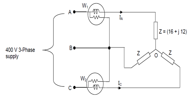
Problem-12: Power measurement by two-watt meter
Across \(400 \mathrm{V}, 3\) -phase supply mains, a star-connected balanced load of \((16+\mathrm{j} 12) \Omega\) impedance is connected.
Taking \(V_a\) as reference, determine the line currents and the power absorbed by the load
If two wattmeters are used to measure the power, what will be the readings of the wattmeters?
Solution-12
\(\quad V_{A}=\frac{400}{\sqrt{3}} \angle 0^{\circ}=230.94 \angle 0^{\circ}~V ~~ Z=(16+j 12)=20 \angle 36.87^{\circ} \Omega\)
- Line currents are:\[\begin{aligned} \mathrm{I}_{\mathrm{A}}&=\frac{\mathrm{V}_{\mathrm{A}}}{\mathrm{Z}}=11.54 \angle-36.87^{\circ} \mathrm{A} \\ \mathrm{I}_{\mathrm{B}}&=11.54 \angle-156.87^{\circ} \mathrm{A}\\ \mathrm{I}_{\mathrm{C}}&=11.54 \angle 83.13^{\circ} \mathrm{A} \end{aligned}\]
- Total power\[P=\sqrt{3} V_{l} I_{l} \cos \theta=\sqrt{3} \times 400 \times 11.54 \cos 36.87^{\circ}=6400 \mathrm{W}\]
- Watt meter readings:\[\begin{aligned} \quad \mathrm{W}_{1}&=\sqrt{3} \mathrm{V}_{\text {ph }} \mathrm{I}_{\text {ph }} \cos \left(\theta+30^{\circ}\right)\\ &=\sqrt{3} \times 230.94 \times 11.54 \cos 66.87^{\circ}=1814.35 \mathrm{W}\\ \mathrm{W}_{2}&=\sqrt{3} \mathrm{V}_{\mathrm{ph}} \mathrm{I}_{\mathrm{ph}} \cos \left(\theta-30^{\circ}\right)\\ & =\sqrt{3} \times 230.94 \times 11.54 \cos 6.87^{\circ}=4585.64 \mathrm{W} \end{aligned}\]