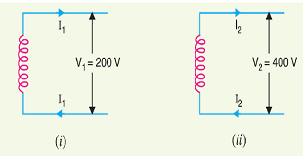
What is the percentage saving in feeder copper if the line voltage in
a 2 -wire d.c. system is raised from 200 volts to 400 volts for the same
power transmitted over the same distance and having the same power
loss?
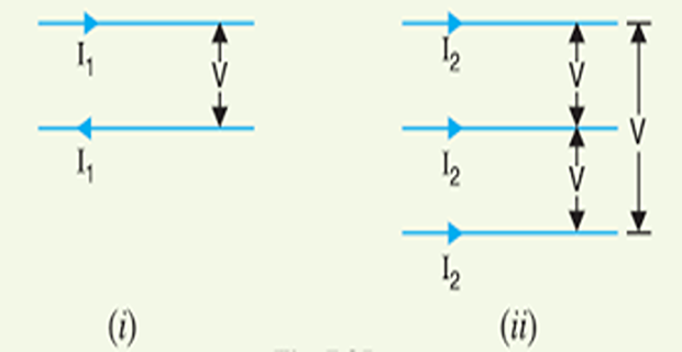
A d.c. 2 -wire system is to be converted into a.c. 3 -phase, 3 -wire
system by the addition of a third conductor of the same cross-section as
the two existing conductors. Calculate the percentage additional load
which can now be supplied if the voltage between wires and the
percentage loss in the line remain unchanged. Assume a balanced load of
unity power factor.
SECTION 04
Solution-2
Let \(R\) be the resistance per
conductor in each case.
i.e. additional power which can be supplied at unity p.f. by 3
-phase, 3 -wire a.c. system =100 %.
SECTION 05
Problem-3
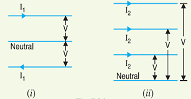
A d.c. 3 -wire system is to be converted into a 3 -phase, 4 -wire
system by adding a fourth wire equal in \(X\) -section to each outer of the d.c.
system. If the percentage power loss and voltage at the consumer’s
terminals are to be the same in the two cases, find the extra power at
unity power factor that can be supplied by the a.c. system. Assume loads
to be balanced.
SECTION 06
Solution-3
Let \(R\) be the resistance per
conductor in each case.
Loads are balanced, neutral wire carries no current.
Consequently, there is no power loss in the neutral
wire.
\[\begin{aligned}
\frac{2 I_{1}^{2} R}{2 V I_{1}} \times 100 & =\frac{3 I_{2}^{2} R}{3
V I_{2}} \times 100 \\
\Rightarrow I_{1} &=I_{2} \\
\frac{P_{2}}{P_{1}} &=\frac{3 V I_{2}}{2 V I_{1}}=\frac{3 V I_{1}}{2
V I_{1}}=1 \cdot 5\\
\Rightarrow P_{2}& =1 \cdot 5 P_{1}
\end{aligned}\]
i.e., extra power that can be supplied at unity power factor by 3
-phase, 4 -wire a.c. system \(=50
\%\)
SECTION 07
Problem-4
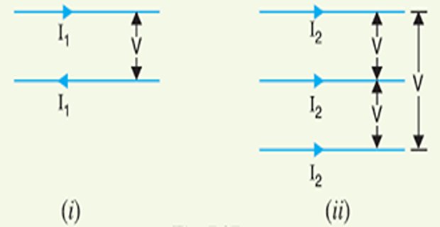
A single phase a.c. system supplies a load of \(200 \mathrm{kW}\) and if this system is
converted to 3 -phase, 3 -wire a.c. system by running a third similar
conductor; calculate the 3 -phase load that can now be supplied if the
voltage between the conductors is the same. Assume the power factor and
transmission efficiency to be the same in the two cases.
SECTION 08
Solution-4
Let \(R\) be the resistance per
conductor and \(\cos \phi\) the power
factor in each case. single phase 2 -wire system.
As the transmission efficiency in the two cases is the same,
therefore, percentage power loss will also be the same
It may be seen that 3 -phase, 3 -wire system can supply \(100 \%\) additional load.
SECTION 09
Problem-5
A \(50 \mathrm{km}\) long
transmission line supplies a load of \(5
\mathrm{MVA}\) at 0.8 p.f. lagging at 33 \(k V .\) The efficiency of transmission is
\(90 \%\). Calculate the volume of
aluminium conductor required for the line when
1-phase, 2-wire system is used
3-phase, 3-wire system is used
The specific resistance of aluminium is \(2
\cdot 85 \times 10^{-8}~ \Omega \mathrm{m}\)
is the area of
cross-section of aluminium conductor. Suppose
\[\text { Line current,
} I_{2}=\frac{\text { Apparent power }}{\sqrt{3} V}=\frac{5 \times
10^{6}}{\sqrt{3} \times 33 \times 10^{3}}=87 \cdot 5 \mathrm{A}\]
Volume of conductor required is the area of
cross-section of the conductor in this case.
Suppose 3 -phase, 3-wire
system
Note that volume of conductor (and hence weight) required is less in
case of 3 -phase, 3 -wire system.
SECTION 11
Problem-6
A sub-station supplies power at \(11
\mathrm{kV}\), 0 8 p.f. lagging to a consumer through a single
phase transmission line having total resistance (both go and return) of
0.15 \(\Omega .\) The voltage drop in
the line is \(15 \%\). If the same
power is to be supplied to the same consumer by two wire d.c. system by
a new line having a total resistance of 0.05 \(\Omega\) and if the allowable voltage drop
is \(25 \%\), calculate the d.c. supply
voltage.
SECTION 12
Solution-6
single phase
system
\[\begin{aligned}
\text { Voltage drop } &=I_{1} R_{1}=I_{1} \times 0 \cdot 15
\text { volts } \\
\text { Also voltage drop } &=\frac{15}{100} \times 11000=1650
\text { volts }
\end{aligned}\]
A 3 -phase, 4 -wire system is used for lighting. Compare the amount
of copper required with that needed for a 2 -wire \(D . C .\) system with same line voltage.
Assume the same losses and balanced load. The neutral is one half the
cross-section of one of the respective outers.
SECTION 14
Solution-7
Two-wire D.C
\[\begin{aligned}
I_{1} &=P V \\
\text { power loss } &=2 I_{1}^{2} R_{1}=2 P^{2} R_{1} / V^{2}
\end{aligned}\]
resistance/conductor Current
power delivered,
voltage between
conductors Let
Three-phase, 4-wire
\[\begin{aligned}
P &=3 V I_{2} \cos \phi=3 V I_{2} \quad-\mathrm{if} \cos \phi=1 \\
\text { Power loss } &=3 I_{2}^{2} R_{2}=3(P / 3 V)^{2} R_{2}=P^{2}
R_{2} / 3 V^{2}
\end{aligned}\]
0.292 \(\times\) Cu
for d.c. system\(3-\phi\)
\[\therefore \quad \frac{\text { Cu for }
3-\phi \text { system }}{\text { Cu for d.c. system }}=\frac{3.5 A_{2}
l}{2 A_{1} l}=\frac{3.5}{2} \times \frac{1}{6}=0.292\]
\(=\left(3 A_{2} l+A_{2} l / 2\right)\)\(3-\phi, 4\)\(=2 A_{1} l\)\(\therefore \quad\)\(R \propto l /
A\)\(A_{1} /
A_{2}=6 .\)\(A_{2}\)\(A_{1}\)
\(\therefore\) resistance of
each phase wire. be the line-to-neutral
voltage and Let
SECTION 15
Problem-8
Estimate the weight of copper required to supply a load of \(100 \mathrm{MW}\) at UPF by a 3-phase, 380
kV system over a distance of 100 km. The neutral point is earthed. The
resistance of mission can be assumed to be 90 percent.
SECTION 16
Solution-8
\[\text { Line
current }=100 \times 10^{6} / \sqrt{3} \times 380 \times 10^{3} \times
1=152~ \mathrm{A}\]