Per-Unit Quantities
Revision of Important Formulas
Problem-1
A three-phase generator with rating 1000 kVA, 33 kV has its armature resistance and synchronous reactance as 20 \(\Omega\)/phase and 70 \(\Omega\)/phase. Calculate p.u. impedance of the generator.
Solution-1
The generator ratings are chosen as base \(\mathrm{kV}\) and base \(\mathrm{kVA}\).
Base kilovolt, \(\mathrm{kV}_{\mathrm{b}}=33 \mathrm{kV}\)
Base kilovoltampere, \(\mathrm{kVA}_{\mathrm{b}}=1000 \mathrm{kVA}\)
- Base impedance\[Z_{b}=\frac{\left(k V_{b}\right)^{2}}{M V A_{b}}=\frac{(33)^{2}}{1000 / 1000}=1089 \Omega\]
- Actual impedance per phase\[\mathrm{Z}=(20+\mathrm{j} 70) \Omega / phase\]
- p.u. impedance\[Z_{\mathrm{pu}}=\frac{\text { Actual impedance }}{\text { Base impedance }}=\frac{Z}{Z_{b}}=\frac{20+j 70}{1089}=0.018+j 0.064 \mathrm{p} . \mathrm{u}\]
Problem-2
A three phase, \(\Delta\) -Y transformer with rating \(100 \mathrm{kVA}, 11 \mathrm{kV} / 400 \mathrm{~V}\) has its primary and secondary leakage reactance as \(12 \Omega /\) phase and \(0.05 \Omega /\) phase respectively. Calculate the p.u. reactance of transformer.
Solution-2
Case-1: HV winding (primary) rating chosen as base value
Base kilovolt, \(\mathrm{kV}_{\mathrm{b}}=11 \mathrm{kV}\)
Base kilo volt-ampere, \(\mathrm{kVA}_{\mathrm{b}}=100 \mathrm{kVA}\)
- Base impedance per phase\[\mathrm{Z}_{\mathrm{b}}=\frac{\left(\mathrm{kV}_{\mathrm{b}}\right)^{2}}{\mathrm{MVA}_{\mathrm{b}}}=\frac{(11)^{2}}{100 / 1000}=1210 \Omega\]
Transformer line voltage ratio, \(\mathrm{K}=\dfrac{400}{11,000}=0.0364\)
- Total leakage reactance referred to primary\[\begin{aligned} \mathrm{X}_{01}&=\mathrm{X}_{1}+\mathrm{X}_{2}^{*}\\ &=\mathrm{X}_{1}+\frac{\mathrm{X}_{2}}{\mathrm{~K}^{2}}\\ &=12+\frac{0.05}{(0.0364)^{2}}=12+37.737 = 49.737 \Omega / \text { phase } \end{aligned}\]
- p. u. reactance per phase\[\begin{aligned} & X_{p u}=\frac{\text { Total leakage reactance }}{\text { Base impedance }}\\ &=\frac{X_{01}}{Z_{b}}=\frac{49.737}{1210}=0.0411 \mathrm{p.u} \end{aligned}\]
Case-2: LV winding (secondary) rating chosen as base value
Base kilovolt, \(\mathrm{kV}_{\mathrm{b}}=400 / 1000=0.4 \mathrm{kV}\)
Base kilovoltampere, \(\mathrm{kVA}_{\mathrm{b}}=100 \mathrm{kVA}\)
- Base impedance per phase\[\mathrm{Z}_{\mathrm{b}}=\frac{\left(\mathrm{kV}_{\mathrm{b}}\right)^{2}}{\mathrm{MVA}_{\mathrm{b}}}=\frac{(0.4)^{2}}{100 / 1000}=1.6 \Omega\]
Transformer line voltage ratio, \(\mathrm{K}=\dfrac{400}{11,000}=0.0364\)
- Total leakage reactance referred to secondary\[\begin{aligned} \mathrm{X}_{02}&=\mathrm{X}_{1}^{\prime}+\mathrm{X}_{2}=\mathrm{K}^{2} \mathrm{X}_{1}+\mathrm{X}_{2}\\ &=(0.0364)^{2} \times 12+0.05\\ &=0.0159+0.05=0.0659 \Omega / \text { phase } \end{aligned}\]
p.u. reactance per phase, \(\mathrm{X}_{\mathrm{pu}}=\dfrac{\text { Total leakage reactance }}{\text { Base impedance }}=\dfrac{\mathrm{X}_{02}}{\mathrm{Z}_{\mathrm{b}}}=\dfrac{0.0659}{1.6}=0.0411 \mathrm{p}\).u.
Note:
It is observed that the p.u. reactance of a transformer referred to primary and secondary are same.
In \(3\phi\) transformer of the voltage ratio K is obtained using line values then using this value of K the phase impedance per phase of star-side can be directly transferred to delta side or vice versa
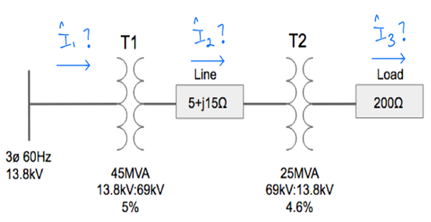
Problem-3
Solution-3
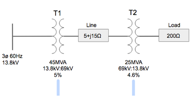
Step-1: Separate by Voltage zones
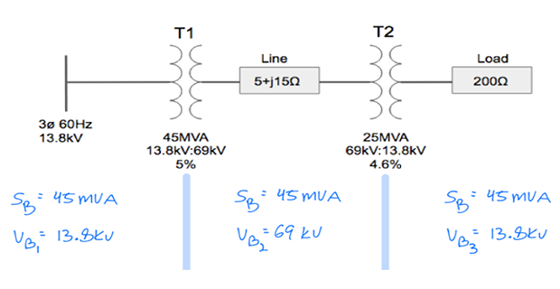
Step-2: Assign base values
Step-3: Calculate \(Z_B\) for each zones
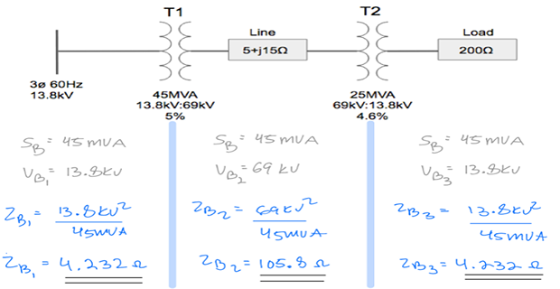
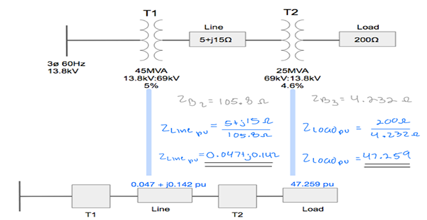
Step-4: Calculate \(Z_{p.u.}\) for each zone
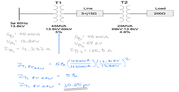
Step-5: Calculate \(Z_{p.u}\) for Tran-1
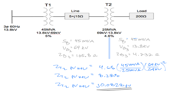
Step-6: Calculate \(Z_{p.u}\) for Tran-2
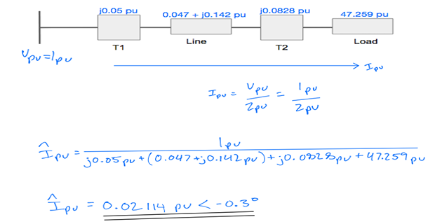
Step-7: Calculate p.u. current and voltages
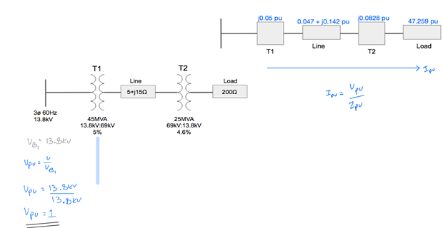
Step-8: Use Ohm’s Law to calculate p.u. current
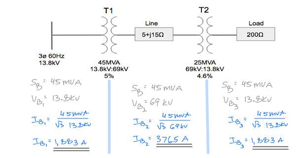
Step-9: Calculate \(I_B\) in each zone
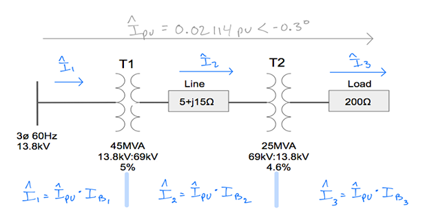
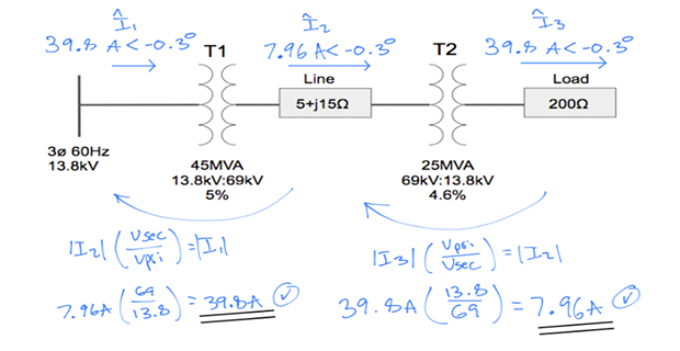
Step-10: Calculate actual current in each zone
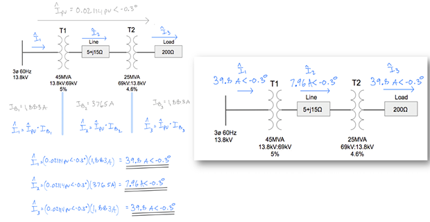
Step-11: Check using T/F ratios