VIDEO
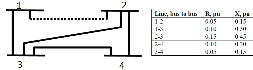
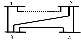
The figure below shows the one line diagram of a simple four bus
system. The table below gives line impedances identified by the buses on
which these terminate. The shunt admittance at all the buses is assumed
to be negligible.
Find YBUS , assuming that the line shown dotted is not
connected.
What modifications need to be carried out in YBUS if the line
shown dotted is connected.
\[\begin{aligned}
&\boxed{R_{p .u}+j X_{p u}} ~\quad \boxed{G_{p u}+j B_{p u}} \\
z_{1-2}~&0.05+j 0.15 \rightarrow 2.0-j 6.0 \\
z_{1-3}~&0.10+j 0.30 \rightarrow 1.0-j 3.0 \\
z_{2-3}~&0.15+j 0.45 \rightarrow 0.66-j 2.0 \\
z_{2-4}~&0.10+j 0.30 \rightarrow 1.0-j 3.0 \\
z_{3-4}~&0.05+j 0.15 \rightarrow 2.0-j 6.0
\end{aligned}\]
\[\begin{aligned}
&\boxed{R_{p .u}+j X_{p u}} ~\quad \boxed{G_{p u}+j B_{p
u}} \\
z_{1-2}~&0.05+j 0.15 \rightarrow 2.0-j 6.0 \\
z_{1-3}~&0.10+j 0.30 \rightarrow 1.0-j 3.0 \\
z_{2-3}~&0.15+j 0.45 \rightarrow 0.66-j 2.0 \\
z_{2-4}~&0.10+j 0.30 \rightarrow 1.0-j 3.0 \\
z_{3-4}~&0.05+j 0.15 \rightarrow 2.0-j 6.0
\end{aligned}\]
\[\begin{aligned}
&Y_{Bus}=\left[\begin{array}{cccc}
y_{13} & 0 & -y_{13} & 0 \\
0 & y_{23}+y_{24} & -y_{23} & -y_{24} \\
-y_{13} & -y_{23} & y_{31}+y_{32}+y_{34} &
-y_{34} \\
0 & -y_{24} & -y_{34} & y_{43}+y_{42}
\end{array}\right] \\
&Y_{Bus}=\left[\begin{array}{cccc}
1-j 3 & 0 & -1+j 3 & 0 \\
0 & 1.66-j 5 & -0.66+j 2 & -1+j 3 \\
-1+j 3 & -0.66+j 2 & 3.66-j 11 & -2+j 6 \\
0 & -1+j 3 & -2+j 6 & 3-j 9\\
\end{array}\right]
\end{aligned}\]
\[\begin{aligned}
&Y_{11,\text{new}}=Y_{11,\text{old}}+(2-j 6)=-3-j 9 \\
&Y_{12,\text{new}}=Y_{12,\text{old}}-(2-j 6)=-2+j
6=Y_{21,\text{new}} \\
&Y_{22,\text { new }}=Y_{22,\text{old}}+(2-j 6)=3.66-j 11
\end{aligned}\]
\[Y_{\text {Bus }}=\left[\begin{array}{cccc}
3-j 9 & -2+j 6 & -1+j 3 & 0 \\
-2+j 6 & 3.66-j 11 & -0.66+j 2 & -1+j 3 \\
-1+j 3 & -0.66+j 2 & 3.66-j 11 & -2+j 6 \\
0 & -1+j 3 & -2+j 6 & 3-j 9
\end{array}\right]\]
Modified Y-Bus:
\[\begin{aligned}
\mathrm{Y}_{11} &=0.0094-\mathrm{j} 0.0134 &
\mathrm{Y}_{44} &=0.0154-\mathrm{j} 0.0231 \\
\mathrm{Y}_{22} &=0.0088-\mathrm{j} 0.0147 &
\mathrm{Y}_{55} &=0.0082-\mathrm{j} 0.0219 \\
\mathrm{Y}_{33} &=0.0186-\mathrm{j} 0.0082 &
\mathrm{Y}_{66} &=0.0176-\mathrm{j} 0.0294
\end{aligned}\]
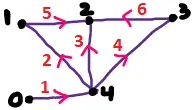
\[
[\hat{A}]=\begin{array}{c|ccccc}
n \rightarrow & 0 & 1 & 2 & 3 & 4 \\
e \downarrow & & & & & \\
\hline 1 & 1 & 0 & 0 & 0 & -1 \\
2 & 0 & -1 & 0 & 0 & 1 \\
3 & 0 & 0 & -1 & 0 & 1 \\
4 & 0 & 0 & 0 & -1 & 1 \\
5 & 0 & 1 & -1 & 0 & 0 \\
6 & 0 & 0 & -1 & 1 & 0
\end{array}
\]
\(\Leftarrow\) Relating branches
and nodes
Matrix rectangular \(\Rightarrow\) singular
\(1/-1\) if element oriented
away/towards the node
\(0\) when no incidence
\[
[\hat{A}]=\begin{array}{c|ccccc}n\to&0&1&2&3&4\\\hline1&1&0&0&0&-1\\2&0&-1&0&0&1\\3&0&0&-1&0&1\\4&0&0&0&-1&1\\5&0&1&-1&0&0\\6&0&0&-1&1&0\end{array}
\]
) Node Column Remove Reference (
\[{\left[A^{\top}\right]=\left[\begin{array}{cccccc}
0 & -1 & 0 & 0 & 1 & 0 \\
0 & 0 & -1 & 0 & -1 & -1 \\
0 & 0 & 0 & -1 & 0 & 1 \\
-1 & 1 & 1 & 1 & 0 & 0
\end{array}\right]}\]
\[\begin{aligned}
\mathrm{Y}_{11} &=0.0094-\mathrm{j} 0.0134 &
\mathrm{Y}_{44} &=0.0154-\mathrm{j} 0.0231 \\
\mathrm{Y}_{22} &=0.0088-\mathrm{j} 0.0147 &
\mathrm{Y}_{55} &=0.0082-\mathrm{j} 0.0219 \\
\mathrm{Y}_{33} &=0.0186-\mathrm{j} 0.0082 &
\mathrm{Y}_{66} &=0.0176-\mathrm{j} 0.0294
\end{aligned}\]
\[Y_{B \cup S}=\left[A^{\top}\right]
\times[Y] \times[A]\]
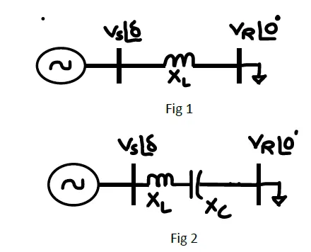
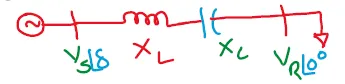
A transmission line represented in fig 1. A series capacitance is
added to improve the performance of the transmission line as shown in
fig 2. calculate the power transferred, if the capacitive reactance to
inductive reactance ratio is
\(0.5\)
\(0.2\)
\[P_{L1} =
\dfrac{V_sV_r}{X_L}\sin\delta~\mathrm{Watts}\]
Adding a capacitor in series: \[P_{L2} =
\dfrac{V_sV_r}{X_L-X_C}\sin\delta~\mathrm{Watts}\]
\[\dfrac{P_{L2}}{P_{L1}} =
\dfrac{1}{1-\left(\dfrac{X_C}{X_L}\right)}\]
\[\begin{aligned}
\dfrac{P_{L2}}{P_{L1}} & = \dfrac{1}{1-0.5} = 2\\
\Rightarrow ~P_{L2} & = 2P_{L1}
\end{aligned}\]
\[\begin{aligned}
\dfrac{P_{L2}}{P_{L1}} & = \dfrac{1}{1-0.2} = 1.25\\
\Rightarrow ~P_{L2} & = 1.25P_{L1}
\end{aligned}\]
 \[P_{L2} = \dfrac{V_sV_r}{X_L-X_C}\sin\delta~\mathrm{Watts}\]