Demonstrative Video
Contents
Lecture-41
Introduction to Unsymmetrical Faults
Lecture-42
Single Line-to-Ground (LG) Fault
Lecture-43
Line-to-Line (LL) Fault
Lecture-44
Double Line-to-Ground (LLG) Fault
Lecture-45
Fault Current Computation Using Sequence networks
Introduction to Unsymmetrical Faults
Unsymmetrical faults: Fault currents in the three-phases are unequal.
Most of the faults that occur on power systems are unsymmetrical faults,
unsymmetrical short circuits,
unsymmetrical faults through impedances,
open conductors.
One or two open conductors result in unsymmetrical faults, through either the breaking of one or two conductors or the action of fuses and other devices that may not open the three phases simultaneously.
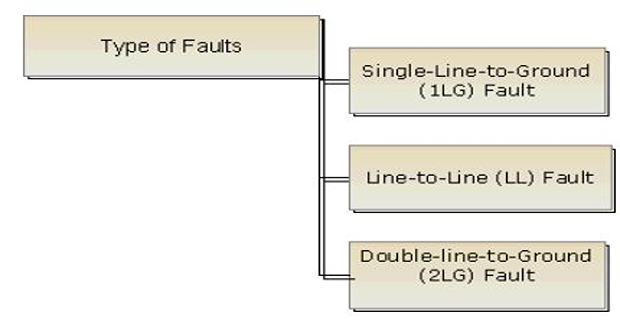
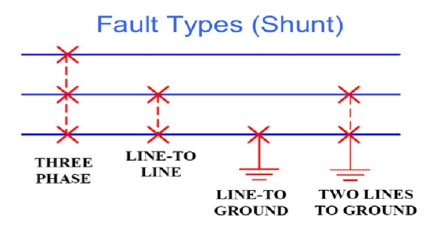
Types of Unsymmetrical faults:

Difference: Symmetrical & Unsymmetrical Faults

The path of \(I_f\) from line to line or line to ground may or may not contain impedance.
Since any unsymmetrical fault causes unbalanced currents to flow in the system, the method of symmetrical components is very used in the analysis to determine the currents and voltages in all parts of the system after the occurrence of the fault.
PS faults will be considered by applying Thévenin’s theorem, which allows us to find \(I_f\) by replacing the entire system by a single generator and series impedance
Bus impedance matrix is applied to the analysis of unsymmetrical faults.
Sequence circuits and networks will be used for finding out \(I_f\) during unsymmetrical faults.
Theory of Unsymmetrical Faults
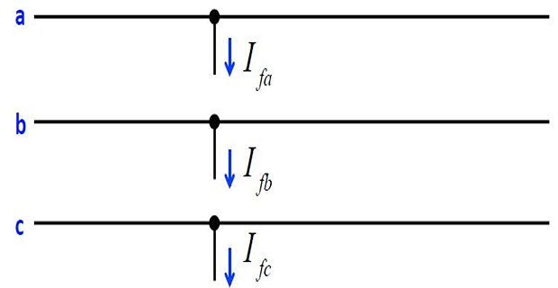
Currents flowing out of the original balanced system from phases \(a,~ b\), and \(c\) at the fault point will be designated as \(I_{fa}, ~ I_{fb}\) and \(I_{fc}\), respectively.

This shows the three lines \(a,~ b\), and \(c\) of the three‐phase system at the part of the network where the fault occurs.
The flow of current from each line into the fault is indicated by arrows shown beside hypothetical stubs connected to each line at the fault location.
Appropriate connections of the stubs represent the various types of fault.
For instance, direct connection of stubs \(b\) and \(c\) produces a line-to-line fault through zero impedance.
The current in stub \(a\) is then zero, and \(l_b\) equals \(l_c\).
The line-to-ground voltages at any bus \(j\) of the system during the fault will be designated \(V_{ja}, V_{jb}, ~and~ V_{jc}\)
Superscripts 1, 2, and 0, respectively, are used to denote positive-, negative-, and zero-sequence quantities.
For e.g.,\(V^{(1)}_{ja}, V^{(2)}_{jb},~ and ~V^{(0)}_{jc}\) will denote, respectively, the positive-, negative-, and zero-sequence components of the line-to-ground voltage at bus \(j\) during the fault.
The line-to-neutral voltage of phase \(a\) at the fault point before the fault occurs will be designated simply by \(V_f\), which is a positive-sequence voltage since the system is balanced.
Pre-fault voltage \(V_f\) is considered previously when calculating the currents with a symmetrical three-phase fault applied.
Calculation of Fault Current
Following assumptions are made:
PS is balanced before the fault occurs such that of the three sequence networks only the positive sequence network is active.
As the fault occurs, the sequence networks are connected only through the fault location.
The fault current is negligible such that the pre-fault positive sequence voltages are same at all nodes and at the fault location.
All the network resistances and line charging capacitances are negligible.
All loads are passive except the rotating loads which are represented by synchronous machines.