Contents
Parameters of the TL
Relation of parameters with Electric and Magnetic field
Types of Conductors
Resistance of TL and variation with temperature
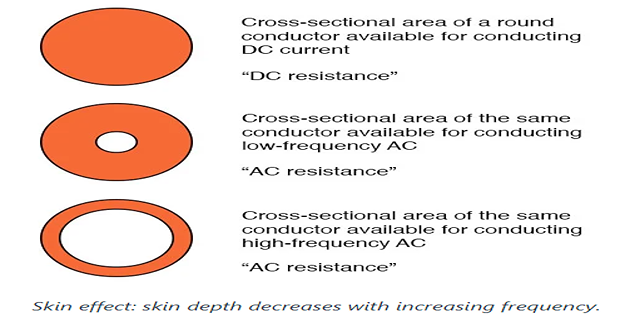
Skin effect
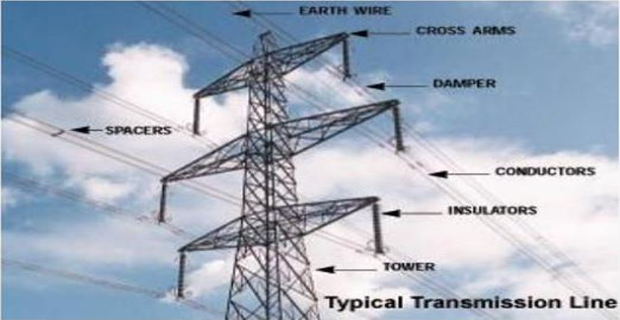
Parameters of the Transmission Line
An electric transmission line has 4 parameters :
Resistance and Inductance form series impedance
Capacitance and Conductance form shunt admittance
Conductance:
exists between conductors or conductors and the ground
accounts for the leakage current at the insulators of overhead lines or through insulation of cables
leakage at insulators of overhead lines is negligible, conductance is neglected
variable no good way to take into account
leakage at insulator change appreciably with atmospheric conditions
conducting properties due to dirt deposit on insulators
Corona variable with atmospheric conditions
effect of conductance is negligible amount of shunt admittance
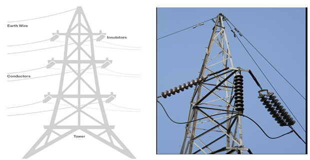
Relation of parameters with electric and magnetic fields
Lines of magnetic flux forms a closed loop linking the circuit
Lines of electric flux originate from the ’+’ charge on one conductor and terminate on the ’-’ charge on the other conductor
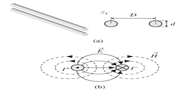
Magnetic and Electric field associated with a two-wire line
Variation of the current causes changes in the number of magnetic flux lines linking the circuit
Change in the flux linkage induce a voltage proportional to the rate of change of flux
Inductance \(\rightarrow\) Voltage induced \(\rightarrow\) Changing flux \(\rightarrow\) Rate of change of current
Capacitance \(\rightarrow\) Charge on the conductors per unit of potential difference between them
Types of conductors
Copper replaced by aluminum
much lower cost
Lighter weight for the same resistance
Al conductor has a larger diameter (advantageous) compared to Cu conductor of the same resistance
lines of electric flux originating on the conductor will be further apart at the conductor surface for the same voltage
lower voltage gradient at the conductor surface
Less tendency to ionize the air around the conductor (Corona)
AAC all-aluminum conductors
AAAC all-aluminum-alloy conductors
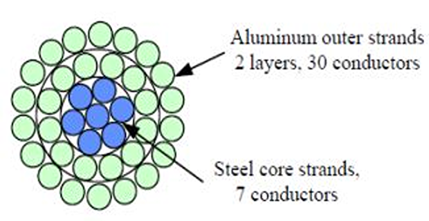
ACSR aluminum conductor steel reinforced
ACAR aluminum conductor alloy reinforced
Al alloy conductors have higher tensile strength as compared to ordinary conductors
ACSR: central core of steel strands surrounded by layers of Al strands
ACAR: central core of higher-strength Al surrounded by layers of electrical-conductor-grade Al
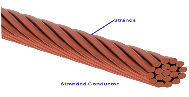
Stranded conductors
Alternate layers of wires are spiraled in opposite direction to prevent unwinding
outer radius of one layer coincide with inner radius of the next layer
provides flexibility for large cross-sectional area
number of strands depends on the number of layers and whether all the strands are of the same diameter
Expanded ACSR:
has filler such as paper separating the inner steel strands from outer Al strands.
Paper gives larger diameter (lower corona) for given conductivity and tensile strength.
Resistance of the transmission line
responsible for power loss in the TL
The effective resistance of the conductor
equals to the dc resistance for uniform current distribution\[R=\dfrac{\mbox{power loss in the conductor}}{|I|^{2}}\Omega\]DC resistance is given by
\[R_{0}=\dfrac{\rho l}{A}~\Omega\]dc resistance of the stranded conductor is greater than computed by \(R_0\) because spiralling of the strands make them longer than the conductor itself
1% for 3 strand and 2% for concentrically stranded conductors
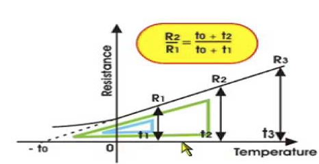
Variation of Resistance with Temperature
practically linear over normal range of operation
extension of the linear portion \(\mapsto\) correction the resistance with temperature
\(\Rightarrow\) point of interaction with \(t\)-axis at zero \(R\) is a constant of the material
Uniform distribution of current through \(A\) occurs only for dc
\(f\) of the ac \(\Uparrow\), non-uniformity becomes more pronounced
Skin Effect
The non-uniform distribution of electric current over the surface or skin of the conductor carrying a.c is called the skin effect.
In other words, the concentration of charge is more near the surface as compared to the core of the conductor.
The ohmic resistance of the conductor is increased due to the concentration of current on the surface of the conductor.
: increase in \(f\) causes non-uniform current distribution
\(\Rightarrow\) circular conductor \(\mapsto\) current density usually increases from the interior towards the surface
\(\Rightarrow\) larger radius conductor \(\mapsto\) current density is oscillatory w.r.t radial distance from the center
Factors affecting Skin Effect
Frequency – increases with the increase in frequency.
Diameter – increases with the increase in diameter of the conductor.
Shape of the conductor – more in the solid conductor and less in the stranded conductor because the surface area of the solid conductor is more.
Type of material – increase with the increase in the permeability of the material.