Demonstrative Video
Transients due to short-circuit
Most of the components of PS have inductive property which give rise to transients when there is a sudden change in current
Faults on PS are accompanied by sudden change in current which give rise to transient condition
Transient states of TL and Synchronous generator are discussed
Transients due to short-circuit in TL
An unloaded TL can be represented by an R-L circuit excited by a sinusoidal source (capacitance neglected)
The problem of calculating the initial current when a system is short-circuited can be approached by considering an ac voltage applied to an RL circuit
.
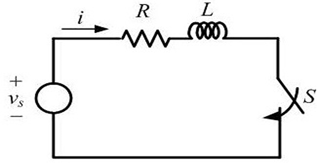
Switch is closed at time \(t = 0\)
Current \(i\) is zero before the closing of the switch
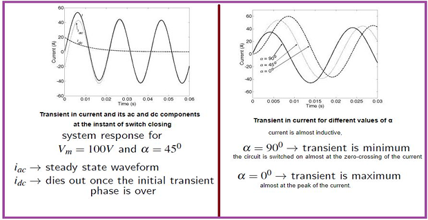
What is the change in the shape of the transient current with the changes in the phase of the source voltage waveform at the instant of closing the switch?
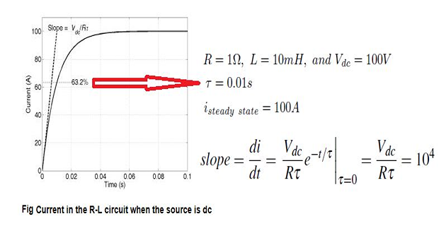
\(\bullet\) DC Source, \(V_s = V_{dc}\)
where \(\tau = L/R\)
\(\bullet\) AC Source
The current response remains unchanged for input dc voltage source
This is not the case when the circuit is excited by an ac source
\[v_{s}=V_{m}sin\left(\omega t+\alpha\right)\]- \[\begin{aligned} i(t) & =i_{ac}(t)+i_{dc}(t)\\ i_{ac} & =\dfrac{\sqrt{2}V_{m}}{Z}sin\left(\omega t+\alpha-\theta\right)\\ i_{dc} & =\dfrac{\sqrt{2}V_{m}}{Z}sin\left(\alpha-\theta\right)e^{-t/\tau}\\ Z & =\sqrt{R^{2}+\left(\omega L\right)^{2}},~\theta=tan^{-1}\left(\dfrac{\omega L}{R}\right) \end{aligned}\]The system response changes with a change in
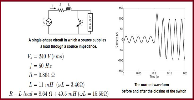
The switch S is suddenly closed creating a short circuit
- \[I=\dfrac{240}{9.504+j19.01}=11.29\angle-63.43^{0}\]\(\sqrt{2} \times 11.29 = 15.97\)\(\rightarrow\)The current phasor before the short circuit occurs is
- \[I=\dfrac{240}{0.864+j3.46}=67.37\angle-75.96^{0}\]\(\sqrt{2} \times 67.37= 95.28\)Once the fault occurs and the system is allowed to reach the steady state, the current phasor is given by
it can be seen that the current rises suddenly and the first peak following the fault is 124 A which is about 30% higher than the post-fault steady-state value.
Peak value of the current will vary with the instant of the occurrence of the fault.
Peak value of the current is nearly 8 times the pre-fault current value in this case.
In general, depending on the ratio of source and load impedances, the faulted current may shoot up anywhere between 10 and 20 times the pre-fault current.
Transient due to Short Circuit in 3-phase Alternator
Calculating \(I_{sc}\) across the terminals of a synchronous generator is very complicated because the internal impedance of the latter varies according to time.
When the power gradually increases, the current reduces passing through three characteristic periods:
Subtransient (enabling determination of the closing capacity of circuit breakers and electrodynamic constraints), average duration, 10 ms
Transient (sets the equipment’s thermal constraints), average duration 250 ms
Permanent (this is the value of the short-circuit current in steady state).
- Typical armature current response when a three-phase symmetrical
short circuit occurs at the terminals of an synchronous generator
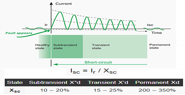
It is assumed that there is no dc offset in the armature current.
The magnitude of the current decreases exponentially from a high initial value.
- \[ i_{f}(t)=\sqrt{2}V_{t}\left[\left(\dfrac{1}{X_{d}^{''}}-\dfrac{1}{X_{d}^{'}}\right)e^{-t/T_{d}^{''}}+\left(\dfrac{1}{X_{d}^{'}}-\dfrac{1}{X_{d}}\right)e^{-t/T_{d}^{'}}+\dfrac{1}{X_{d}}\right]sin\left(\omega t+\alpha-\pi/2\right) \]\[\begin{array}{cc} X_{d}^{''}/T_{d}^{''} & \mbox{direct axis subtransient reactance/time constant}\\ X_{d}^{'}/T_{d}^{'} & \mbox{direct axis transient reactance/time constant}\\ X_{d} & \mbox{direct axis synchronous reactance} \end{array}\]\(\alpha\)\(V_t\)The instantaneous expression for the fault current is given by\[X_{d}^{''}<X_{d}^{'}<X_{d}\]. we have neglected the effect of the armature resistance hence
- \[I_{f}\left(0\right)=I_{f}^{''}=\dfrac{V_{t}}{X_{d}^{''}}\]. Then, rms value of the current Let us assume that the fault occurs at time
The duration of the sub-transient current is dictated by the time constant \(T_{d}^{''}\).
As the time progresses and \(T_{d}^{''}<t<T_{d}^{'}\) , the first exponential term will start decaying and will eventually vanish.
- \[I_{f}^{'}=\dfrac{V_{t}}{X_{d}^{'}}\]is still nearly equal to zero, we have the following rms value of the current However since
- \[I_{f}=\dfrac{V_{t}}{X_{d}}\]As the time progress further and the second exponential term also decays, we get the following rms value of the current for the sinusoidal steady state
In addition to the ac, the fault currents will also contain the dc offset.
Note that a symmetrical fault occurs when three different phases are in three different locations in the ac cycle. Therefore the dc offsets in the three phases are different.
- \[i_{dc}^{max}=\sqrt{2}I_{f}^{''}e^{-t/T_{A}}\]\(T_A\)The maximum value of the dc offset is given by