Swing Equation
The equation governing the rotor dynamics
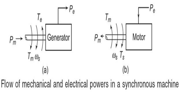
where\[J\dfrac{d^{2}\theta}{dt^{2}}=T_{m}-T_{e}=T_{a}\]
Neglecting the losses, the difference between \(T_m\) and \(T_e\) gives the net accelerating torque \(T_a\) .
In the steady state, \(T_m = T_e\), and hence \(T_a = 0\).
During this period the rotor will move at synchronous speed \(\omega_s\) in rad/s.
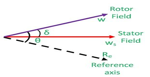
The angular position \(\theta\) is measured with a stationary reference frame.
- \(\delta\)To represent it with respect to the synchronously rotating frame, we define\[\theta=\omega_{s}t+\delta\]
- Defining the angular speed of the rotor as\[\begin{aligned} \omega_{r} & =\dfrac{d\theta}{dt}\\ \omega_{r}-\omega_{s} & =\dfrac{d\delta}{dt} \end{aligned}\]
Therefore, the rotor angular speed is equal to the synchronous speed only when \(d\delta/dt = 0\)
We can therefore term \(d\delta/dt\) as the error in speed.
- \(P_a\)\(P_e\)\(P_m\)Then,\[\begin{aligned} J\dfrac{d^{2}\delta}{dt^{2}} & =T_{m}-T_{e}=T_{a}\\ \Rightarrow J\omega_{r}\dfrac{d^{2}\delta}{dt^{2}} & =P_{m}-P_{e}=P_{a} \end{aligned}\]
- as We now define a normalized\[\begin{aligned} H&=\dfrac{\mbox{Stored Kinetic energy at synchronous speed in mega-joules}}{\mbox{Generator MVA rating}}\\ &=\dfrac{J\omega_{s}^{2}}{2G_{rated}} \end{aligned}\]
- we get Substituting for\[\left[2H\dfrac{G_{rated}}{\omega_{s}^{2}}\right]\omega_{r}\dfrac{d^{2}\delta}{dt^{2}}=P_{m}-P_{e}=P_{a}\]
In steady state, the machine angular speed is equal to the synchronous speed and hence we can replace \(\omega_r\) in the above equation by \(\omega_s\).
Note \(P_m\), \(P_e\) and \(P_a\) are given in MW.
Therefore dividing them by the generator MVA rating, \(G_{rated}\) we can get these quantities in per unit.
- we get Hence dividing both sides by\[\dfrac{2H}{\omega_{s}}\dfrac{d^{2}\delta}{dt^{2}}=P_{m}-P_{e}=P_{a}~\text{per-unit}\]
Equation describes the behaviour of the rotor dynamics and hence is known as the .
The angle \(\delta\) is the angle of the internal emf of the generator and it dictates the amount of power that can be transferred. This angle is therefore called the .
- Let,\[\begin{aligned} G_{mach} & = \mbox{machine rating (base)}\\ G_{system} & = \mbox{system base} \end{aligned}\]
- Then,\[\begin{aligned} \dfrac{G_{mach}}{G_{system}}\left(\dfrac{H_{mach}}{\pi f}\dfrac{d^{2}\delta}{dt^{2}}\right) & =\left(P_{m}-P_{e}\right)\dfrac{G_{mach}}{G_{system}}\\ \Rightarrow\dfrac{H_{system}}{\pi f}\dfrac{d^{2}\delta}{dt^{2}} & =\left(P_{m}-P_{e}\right) \end{aligned}\]
- where\[H_{system}=H_{mach}\left(\dfrac{G_{mach}}{G_{system}}\right)\]
- Consider the swing equations of two machines on a common system base.\[\begin{aligned} \dfrac{H_{1}}{\pi f}\dfrac{d^{2}\delta_{1}}{dt^{2}} & =P_{m1}-P_{e1}\\ \dfrac{H_{2}}{\pi f}\dfrac{d^{2}\delta_{2}}{dt^{2}} & =P_{m2}-P_{e2} \end{aligned}\]
- Since the machine rotors swing together (coherently or in unison)\[\delta_{1} = \delta_{2} = \delta\]
- \[\dfrac{H_{eq}}{\pi f}\dfrac{d^{2}\delta}{dt^{2}}=P_{m}-P_{e}\]Adding\[\begin{aligned} P_{m} & =P_{m1}+P_{m2}\\ P_{e} & =P_{e1}+P_{e2}\\ H_{eq} & =H_{1}+H_{2} \end{aligned}\]
- The two machines swinging coherently are thus reduced to a single machine. The equivalent inertia can be written as\[H_{eq}=\dfrac{H_{1,mach}G_{1,mach}}{G_{system}}+\dfrac{H_{2,mach}G_{2,mach}}{G_{system}}\]
The above results can be easily extendable to any number of machines swinging coherently.