Lecture-4: Overview
Electric power Generation (G), Transmission (T), & Distribution (D)
Electric Supply System
Structure of Power System (PS)
Typical a.c Power Supply Scheme
GTD Systems and Feeders
Introduction
Early days very little demand for electrical energy, so small PS built to supply lighting and heating loads
Modern civilisation needs bulk electrical energy economically and efficiently
Increased electrical energy demand can be met by building big PS at favourable places where fuel (coal, gas, or water) is available in abundance
Shifted the site of PS to places quite away from the consumers
Electrical energy produced at PS has to be supplied to the consumers.
Large network of conductors between PS & consumers.
Network divided into two parts viz., transmission and distribution
Electric Power GTD
The conveyance of electric power from a PS to consumers’ premises is
known as electric supply
system 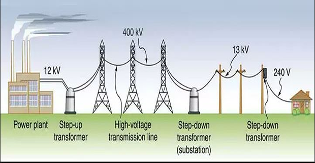
Electric power plant located quite away from the consumers
Power transmitted over large distances using TL
DS distributes power to a large number of small & big consumers
Electric Supply System
The electric supply system can be broadly classified into
d.c. or a.c. system
overhead (OH) or underground (UG) system
G & T of electric power is done by \(3-\phi\), 3-wire a.c. system
Electric power distribution done by \(3-\phi\), 4-wire a.c. system.
UG system is more expensive than the OH system.
OH system is mostly adopted for T & D of electric power.
UG is employed in certain densely populated cities for distribution.
Eliminates danger to human life, avoid ugly appearance, and inconvenience of pole lines running down the main thorough fares.
Structure of Power Systems
Electric PS vary in size and structural components
However they have same basic characteristics:
comprised of \(3-\phi\) ac systems at constant voltage
G & T facilities use \(3-\phi\) equipment
Industrial load are invariably \(3-\phi\)
\(1-\phi\) residential & commercial loads are distributed equally among the phases to form a balanced \(3-\phi\) system
Synchronous machines are used for generation of electricity
Prime movers convert the primary energy sources (fossil, nuclear, and hydraulic) to mechanical energy
Transmit power over significant distances to consumers spread over a wide area that requires transmission system comprising subsystems operating different voltage levels
Electric power produced at GS transmitted to consumers through a complex networks containing TL, T/F, & switching devices
Basic Elements & Structure of a PS
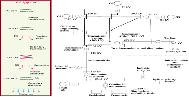
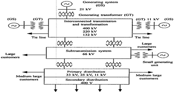
Typical a.c. Power Supply Scheme
Classification of Power System
Generating station
Primary transmission
Secondary transmission
Primary distribution
Secondary distribution
Generating station
Electric power is produced in G.S. by \(3\phi\) alternators operating in parallel.
Generation voltage is 11 kV (6·6 or 33 kV in certain cases)
For economy, generation voltage (11 kV) is stepped upto 132 kV (depending upon the length of TL and the amount of power to be transmitted) with the help of \(3\phi\) T/F.
Advantages of HV transmission includes saving of conductor material and high transmission efficiency.
There is a limit to which this voltage can be increased.
Increase in transmission voltage introduces insulation problems & increase cost of switchgear and transformer equipment
Proper transmission voltage choice is a question of economics
Primary transmission is carried at 66/132/220/ 400 kV
Transmission systems
Primary Transmission:
Electric power at 132 kV is transmitted by \(3\phi\), 3-wire OH system to the outskirts of the city
Secondary transmission:
Primary TL terminates at the receiving station (RS) usually lies at the outskirts of the city.
At RS, voltage is reduced to 33 kV by step-down T/F.
From this station, electric power is transmitted at 33 kV by \(3-\phi\), 3-wire OH system to various SS located at the strategic points in the city.
Distribution systems
Primary Distribution:
Secondary TL terminates at SS, voltage reduced from 33 to 11 kV, \(3-\phi\), 3-wire.
The 11 kV lines run along the important road sides of the city
Big consumers ( demand \(>\) 50 kW) are supplied power at 11 kV for further handling with their own SS.
Secondary Distribution:
Electric power from primary DL (11 kV) is delivered to DS
DS step down the voltage to 400 V, \(3-\phi\), 4-wire
Between any two phases is 400 V and between any phase and neutral is 230 V.
\(1-\phi\) residential lighting load is connected between any one phase and neutral, whereas \(3-\phi\) loads are connected across \(3-\phi\) lines directly.
Feeders
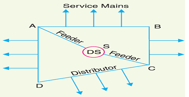
Secondary DS consists of feeders, distributors and service mains
Feeders (SC or SA) radiating from DS supply power to the distributors (AB, BC, CD and AD)
No consumer is given direct connection from the feeders
Consumers are connected to the distributors through their service mains.