Contents
Lecture-26: Single Line Diagram (SLD)
Lecture-27: Per-Unit Quantities & Systems
Lecture-28: Impedance & Reactance diagram
Lecture-29: Formation of Bus Admittance Matrix
Lecture-30: Formation of Bus Impedance Matrix
Lecture-31: Symmetrical components
Lecture-32: Sequence Impedance & Sequence Networks
Representation of Power System
A typical PS consists of a 3-phase grid to which all generating stations feeds energy and from which all substations taps energy
GRID: either a 3-phase single or double circuit TL, running throughout the length and breadth of a country or a state
The components of PS are:
Generating Stations (Alternators)
Power Transformers
Transmission Lines
Substations (Substation Transformers)
Distribution transformers
Loads- Synchronous motors, induction motors, lights etc.
The various components of PS and their interconnections are usually represented by Single Line Diagram (SLD)
In SLD the components are represented by standard symbols and their interconnections are shown by single line, even though they are 3-phase circuits
Single Line Diagram (One-Line Diagram)
A balanced \(3\phi\) system is always analysed on per phase basis by considering one of the \(3\phi\) line and neutral.
It is enough if we show one phase and neutral in the diagrammatic representation of power system
The diagram is further simplified by omitting the neutral and so the resultant diagram will be a SLD
A SLD is diagrammatic representation of PS in which the components are represented by their symbols and the interconnection between them are shown by straight lines
Besides the symbols the rating and the impedance of the components are also marked on the SLD
The purpose of the SLD is to supply in concise form the significant information about the system.
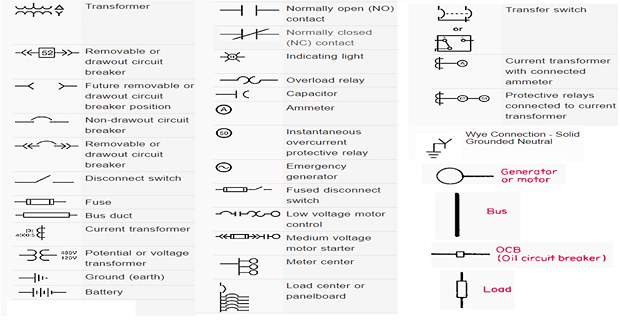
Symbols Used in SLD

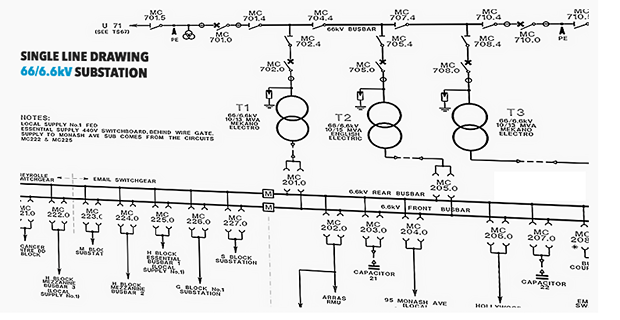
A typical SLD

Identify the Appropriate Symbols
Draw the Required System
Impedance representation in Per-unit Values