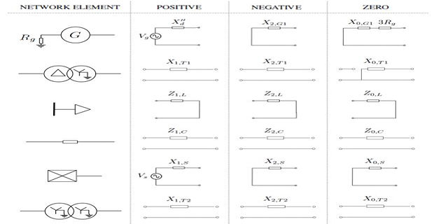
Sequence Impedance & Sequence Networks
Sequence impedances are impedances offered by the power system components to positive, negative, and zero sequence currents.
positive sequence current \(\rightarrow\) positive sequence impedance
negative sequence current \(\rightarrow\) negative sequence impedance
zero sequence current \(\rightarrow\) zero sequence impedance
\(\mathrm{V_{drop}}\) caused by current of a certain sequence depends on the impedance of the element to that sequence current.
Impedance or reactance diagram formed using the impedances of any one sequence only is called sequence network for that particular sequence.
positive sequence impedance \(\rightarrow\) positive sequence network
negative sequence impedance \(\rightarrow\) negative sequence network
zero sequence impedance \(\rightarrow\) zero sequence network
Sequence Circuits for Loads
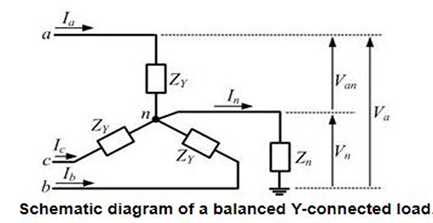
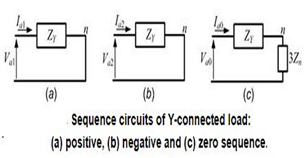
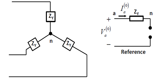
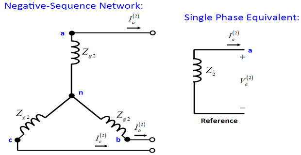
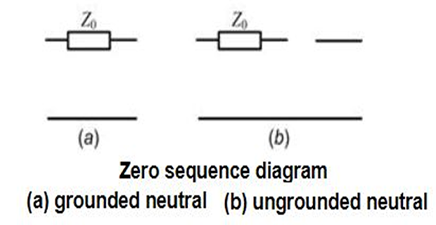
There will not be any positive or negative sequence current flowing out of the neutral point.
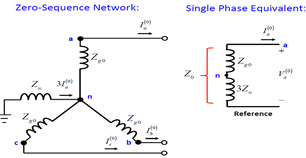
- The voltage drop between the neutral and ground is\[V_{n}=3Z_{n}I_{a0}\]
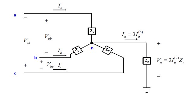
We then find that the zero, positive and negative sequence voltages only depend on their respective sequence component currents.
- , the zero sequence impedance is equal to While the positive and negative sequence impedances are both equal to\[Z_{0}=Z_{Y}+3Z_{n}\]
If the neutral is grounded directly (i.e., \(Z_n = 0\)), then \(Z_0 = Z_Y\).
If the neutral is kept floating (i.e., \(Z_n = \infty\) ), then there will not be any zero sequence current flowing in the circuit at all.
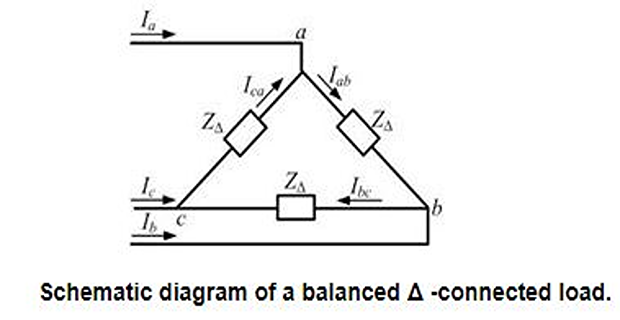
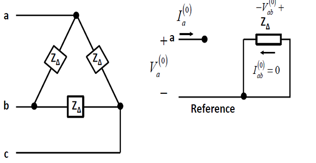
No zero sequence circulating current for a \(\varDelta\)-connected load
Positive and negative sequence impedance for this load will be equal to \(Z_{\varDelta}\).
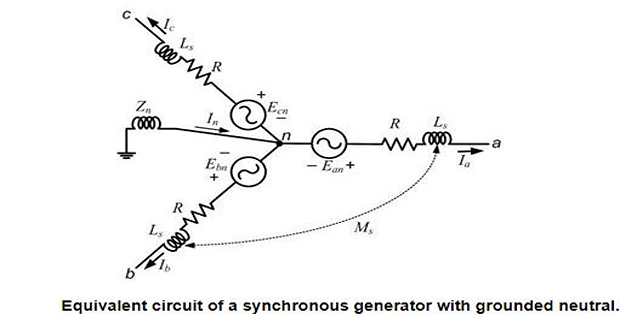
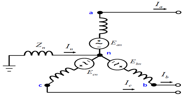
Sequence Circuits for Synchronous Generator
Pre-multiplying both sides by the transformation matrix \(C\), we get
- We can separate the terms\[\begin{aligned} V_{an0} & =-\left[R+j\omega\left(L_{s}-2M_{s}\right)\right]I_{a0}=-Z_{g0}I_{a0}\\ V_{an1} & =-\left[R+j\omega\left(L_{s}+M_{s}\right)\right]I_{a1}+E_{an}=E_{an}-Z_{1}I_{a1}\\ V_{an2} & =-\left[R+j\omega\left(L_{s}+M_{s}\right)\right]I_{a2}=-Z_{2}I_{a2} \end{aligned}\]
For a Y-connected load \(V_{a1} = V_{an1}\), \(V_{a2} = V_{an2}\) since the neutral current does not affect these voltages.
However \(V_{a0} = V_{an0} + V_n\).
Also we know that \(V_n = - 3Z_nI_{a0}\).
- We can therefore rewrite\[\begin{aligned} V_{a0}&=-\left(Z_{g0}+3Z_{n}\right)I_{a0}\\ &=-Z_{0}I_{a0} \end{aligned}\]
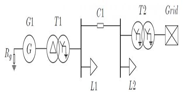
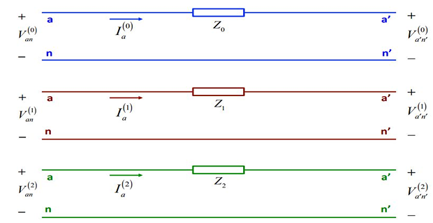
Sequence Circuits for Transmission Line
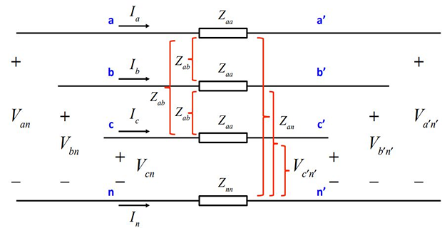
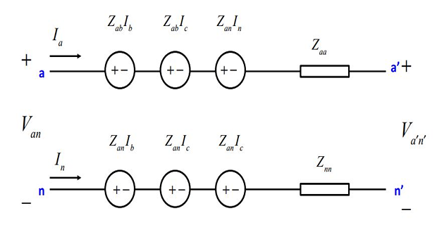
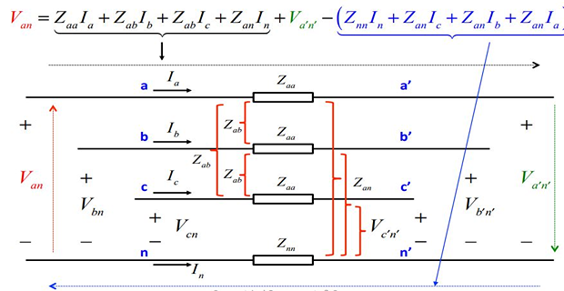
- Since the neutral provides a return path for the currents\[I_{n}=-\left(I_{a}+I_{b}+I_{c}\right)\]
- Therefore on substitution , for phase-a of the circuit\[\begin{aligned} V_{an}-V_{a^{'}n^{'}} & =\left(Z_{aa}+Z_{nn}-2Z_{an}\right)I_{a}+\left(Z_{ab}+Z_{nn}-2Z_{an}\right)\left(I_{b}+I_{c}\right)\\ \Rightarrow V_{aa^{'}} & =Z_{s}I_{a}+Z_{m}\left(I_{b}+I_{c}\right) \end{aligned}\]
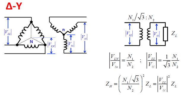
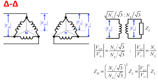
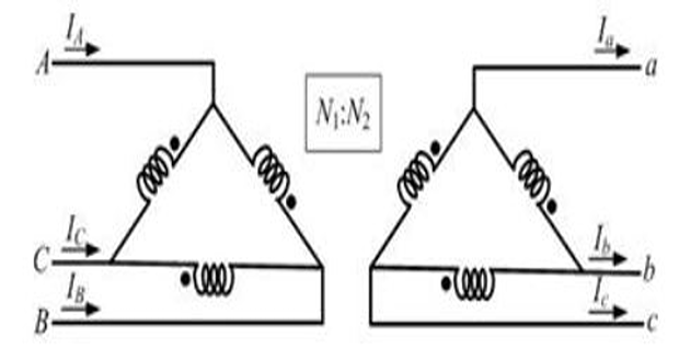
Quick revision of Transformer Connection
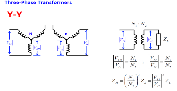
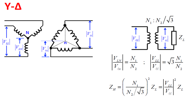
Sequence Circuits for Transformers
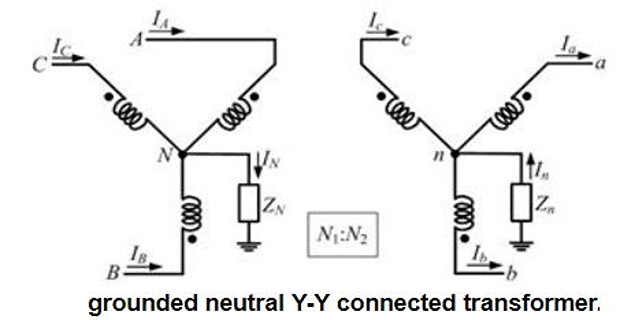
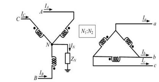
Direction of \(I_n\) is opposite to that of \(I_N\), we can write an similar equation for the secondary side as
\[\begin{aligned} V_{a0}+V_{a1}+V_{a2} & =V_{an0}+V_{an1}+V_{an2}-3Z_{n}I_{a0}\\ & =\dfrac{1}{\alpha}\left(V_{AN0}+V_{AN1}+V_{AN2}\right)-3Z_{n}\alpha I_{A0}\\ \alpha\left(V_{a0}+V_{a1}+V_{a2}\right) & =V_{AN0}+V_{AN1}+V_{AN2}-3Z_{n}\alpha^{2}I_{A0}\\ & =V_{A0}+V_{A1}+V_{A2}-3\left(Z_{N}+Z_{n}\alpha^{2}\right)I_{A0} \end{aligned}\]\[\begin{aligned} \alpha & =\dfrac{N_{1}}{N_{2}} =\dfrac{V_{AN}}{V_{an}}\\ \Rightarrow V_{an}&=\dfrac{V_{AN}}{\alpha}\\ N_{1}I_{A} & =N_{2}I_{a}\Rightarrow I_{a}=\alpha I_{A} \end{aligned}\]
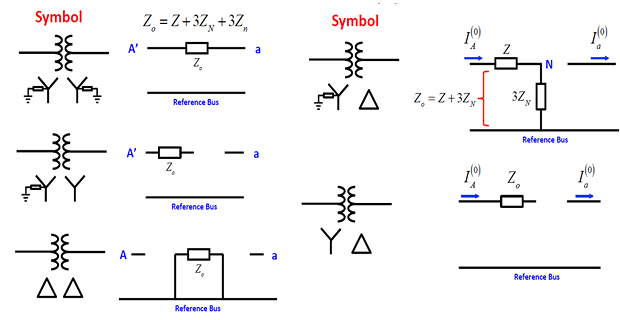
- Separating out the positive, negative and zero sequence components\[\begin{aligned} \alpha V_{a1} & =\dfrac{N_{1}}{N_{2}}V_{a1}=V_{A1}\\ \alpha V_{a2} & =\dfrac{N_{1}}{N_{2}}V_{a2}=V_{A2}\\ \alpha V_{a0} & =\dfrac{N_{1}}{N_{2}}V_{a0}=V_{A0}-3\left[Z_{N}+\left(N_{1}/N_{2}\right)^{2}Z_{n}\right]I_{A0} \end{aligned}\]
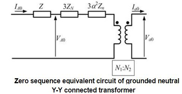
the positive and negative sequence impedances are the same as the transformer leakage impedance \(Z\)
- The total zero sequence impedance is given by\[Z_{0}=Z+3Z_{N}+3\left(N_{1}/N_{2}\right)^{2}Z_{n}\]
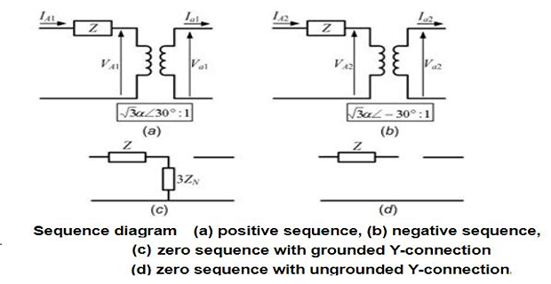
- can be written in terms of the sequence components of the line-to-neutral voltage as The sequence components of the line-to-line voltage\[\begin{aligned} V_{AB1} & =\sqrt{3}V_{AN1}\angle30^{0}\\ V_{AB2} & =\sqrt{3}V_{AN2}\angle-30^{0} \end{aligned}\]
- Therefore combining we get\[\begin{aligned} \sqrt{3}V_{AN1}\angle30^{0}+\sqrt{3}V_{AN2}\angle-30^{0}&=\\ \alpha\left(\sqrt{3}V_{an1}\angle30^{0}+\sqrt{3}V_{an2}\angle-30^{0}\right)& \end{aligned}\]
- Hence we get\[V_{AN1}=\alpha V_{an1}~\quad~V_{AN2}=\alpha V_{an2}\]
Thus the positive and negative sequence equivalent circuits are represented by a series impedance that is equal to the leakage impedance of the transformer.
- -connected winding does not provide any path for the zero sequence current to flow we have Since the\[I_{A0}=I_{a0}=0\]
However the zero sequence current can sometimes circulate within the \(\varDelta\) windings.
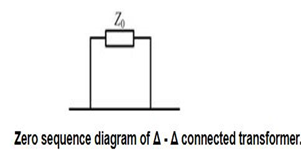
Even though \(I_0\) in the primary Y-connected side has a path to the ground, the \(I_0\) flowing in the \(\varDelta\)-connected secondary winding has no path to flow in the line.
Hence we have \(I_{a0} = 0\).
However the circulating \(I_0\) in the \(\varDelta\) winding magnetically balances the \(I_0\) of the primary winding.
- The voltage in phase-a of both sides of the transformer\[V_{AN}=\dfrac{N_{1}}{N_{2}}V_{ab}=\alpha V_{ab}\]
- Also\[\begin{aligned} V_{A} & =V_{AN}+V_{N}\\ \left(V_{A0}+V_{A1}+V_{A2}\right) & =\left(V_{AN0}+V_{AN1}+V_{AN2}\right)+3Z_{N}I_{A0}\\ & =\alpha\left(V_{ab0}+V_{ab1}+V_{ab2}\right)+3Z_{N}I_{A0} \end{aligned}\]
- Separating zero, positive and negative sequence components\[\begin{aligned} V_{A0} & =\alpha V_{ab0}+3Z_{N}I_{A0}\\ V_{A1} & =\alpha V_{ab1}=\sqrt{3}\alpha V_{a1}\angle30^{0}\\ V_{A2} & =\alpha V_{ab2}=\sqrt{3}\alpha V_{a2}\angle-30^{0} \end{aligned}\]
The zero sequence is \(Z_0 = Z + 3Z_N\).
Note that the primary and the secondary sides are not connected and hence there is an open circuit between them.
However since the zero sequence current flows through primary windings, a return path is provided through the ground.
If however, the neutral in the primary side is not grounded, i.e., \(Z_N = \infty\), then the zero sequence current cannot flow in the primary side as well.
The sequence diagram is then shown as \(Z_0 = Z\).
Zero sequence networks for different T/F Configuration
Sequence Networks
positive, negative & zero sequence networks are formed separately by combining the sequence circuits of all the individual elements.
Assumptions made while forming sequence networks are:
Apart from syn. M/C, network is made of static elements.
\(\mathrm{V_{drop}}\) caused by the current in a particular sequence depends only on the impedance of that part of the network.
Positive & negative sequence impedances are equal for all static circuit components, while zero sequence component need not be the same
Sub-transient positive & negative sequence impedances of a synchronous M/C are equal.
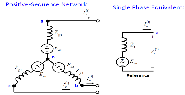
Voltage sources are connected to the positive sequence circuits of the rotating machines.
No \(I_1\) or \(I_2\) flows between neutral and ground.
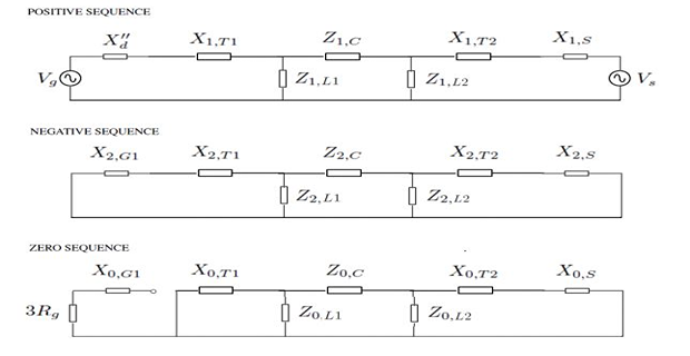
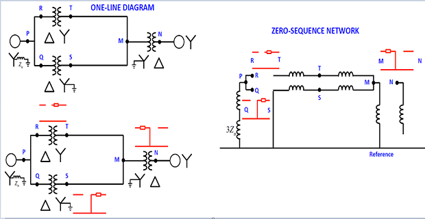
Sequence Network of a Power System