Per Unit Quantities & System
In PSA calculation of impedances, currents, voltages, and powers are done in p.u values (scaled or normalized) rather than using the physical values of \(\Omega\), A, KV, and KVA
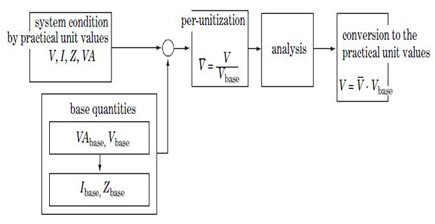
- Per-unit value of any quantity can be defined as\[\mbox{Quantity in p.u} = \dfrac{\mbox{physical value of quantity}}{\mbox{base value of quantity}}\]
Dimensional quantity
Advantages of P.U. System
Network analysis becomes simpler as all impedances can be directly added together regardless of the system voltages
It eliminates factors 3 or \(\sqrt{3}\) multiplication and divisions required on converting \(3-\phi\) to \(1-\phi\) associated with Y/\(\varDelta\) quantities as they are directly taken into account by base quantities
Usually, the impedance of an electrical apparatus is given in % or p.u values by the manufacturer on the nameplate rating
Differences in operating characteristics of many electrical apparatus can be estimated by a comparison of their constants expressed in pu
P.U. impedances of machines of the same type or widely different ratings usually lie within a narrow range, although the ohmic values differ widely for M/Cs of different ratings
P.U. quantities are more convenient in calculations involving digital computers
P.U of Single-Phase System
Any two of the four base quantities (i.e. base voltage, base current, bases VA, and base impedance) are arbitrarily specified, the other two can be determined
Base voltage is selected such that system voltage is normally close to unity
Base VA is usually selected as the KVA or MVA rating of one of the machine or transformer in the system, or a convenient round number such as 1, 10, 100, or 1000 MVA depending on the system size
\(\Rightarrow\) Base quantity is
always real number
\(\Rightarrow\) Physical quantity can
be complex number
Converting per-unit values to physical values
Change of base
In general, the pu impedance of a given apparatus is given on the base of its own VA and voltage ratings, and consequently on the basis of its own impedance base
When such an apparatus is used in a system that has its own base, it becomes necessary to refer all the given base values to the system base values
Assuming the pu impedance of the apparatus is given on the basis of its nameplate ratings as
\[Z_{pu\left(given\right)}=Z_{actual}\dfrac{MVA_{B\left(given\right)}}{\left[kV_{B\left(given\right)}\right]^{2}}\]
For the new set of voltage and VA bases
\[Z_{pu\left(new\right)}=Z_{actual}\dfrac{MVA_{B\left(new\right)}}{\left[kV_{B\left(new\right)}\right]^{2}}\]On dividing
$$\boxed{ Z_{p u(\text { new })}=Z_{p u(\text { given })}\left[\frac{M V A_{B(\text { new })}}{M V A_{B(\text { given })}}\right]\left[\frac{k V_{B(\text { given })}}{k V_{B(\text { new })}}\right]^2 }$$
P.U of Three-Phase System
Per-Unit Representation of a Transformer
a \(3-\phi\) transformer forming part of a \(3-\phi\) system can be represented by a \(1-\phi\) transformer in obtaining per phase solution of the system
The \(\varDelta\)-connected winding is replaced by an equivalent \(Y\) so that the transformation ratio of the equivalent \(1-\phi\) is always the line-to-line voltage ratio of the \(3-\phi\) transformer
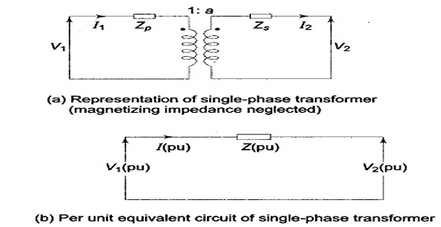
- \[\dfrac{V_{1B}}{V_{2B}} = \dfrac{1}{a}\]\[\begin{aligned} V_{2} & =\left(V_{1}-I_{1}Z_{p}\right)a-I_{2}Z_{s}\\ \Longrightarrow V_{2\left(pu\right)}V_{2B} & =\left[V_{1\left(pu\right)}V_{1B}-I_{1\left(pu\right)}I_{1B}Z_{p\left(pu\right)}Z_{1B}\right]a-\\ &I_{2\left(pu\right)}I_{2B}Z_{s\left(pu\right)}Z_{2B}\\ \Longrightarrow V_{2\left(pu\right)} & =V_{1\left(pu\right)}-I_{1\left(pu\right)}Z_{p\left(pu\right)}-I_{2\left(pu\right)}Z_{s\left(pu\right)} \end{aligned}\]\((VA)_{B}\)\(\dfrac{I_{1B}}{I_{2B}} = a\) and voltage bases on two sides of a transformer in the ratio of transformation, i.e. Let us choose\[Z_{1B}=\dfrac{V_{1B}}{I_{1B}},~Z_{2B}=\dfrac{V_{2B}}{I_{2B}}\]
\(\Longrightarrow\) represents a simple equivalent circuit without ideal transformer.
Thus, considerable simplification has been achieved with pu method
- On secondary side, \(Z_{eq}\)\(Z_{pu}\)\[\begin{aligned} Z_{1} & =Z_{p}+Z_{s}/a^{2}\\ \Longrightarrow\dfrac{Z_{1}}{Z_{1B}} & =\dfrac{Z_{p}}{Z_{1B}}+\dfrac{Z_{s}}{a^{2}Z_{1B}}~\left(NOTE:~a^{2}Z_{1B}=Z_{2B}\right)\\ \Longrightarrow Z_{1\left(pu\right)} & =Z_{p\left(pu\right)}+Z_{s\left(pu\right)}=Z_{\left(p\right)} \end{aligned}\]
Thus, \(Z_{1\left(pu\right)} = Z_{2\left(pu\right)}\) provided voltage bases on the two sides are in the ratio of transformation.